How do I document a smart home installation from the distribution board to the dossier? A KNX apartment as a worked example
Distribution board with modules and terminals, channel plan for the board door, terminal plan, functions by room, bus lines with bus budget and a dossier as draft or final – for KNX, Niko Home Control, Loxone, Shelly, Sonoff or vendor-neutral planning. Shown on a fictitious Brussels KNX apartment, with all limits.
 AuthorStephan Behm
PlanElec plans and documents smart home installations for integrators and electricians from one project: the distribution board with modules, rails, terminals and wiring, the channel plan for the board door as PDF or CSV, the terminal plan, the functions by room, bus lines with a bus budget and the smart home dossier as draft or final. This works for every supported automation system: KNX, Niko Home Control, Loxone, Shelly, Sonoff or vendor-neutral planning. In the team you comment directly on a module, hand out tasks and have documents approved. This article walks through a fictitious Brussels apartment with seven rooms, planned with KNX, with real images from PlanElec. For KNX there is an add-on at the end: proposed addresses and a group address file for ETS.
As of 4 November 2026. The step-by-step guide is in the help centre: Plan and document a smart home installation: step by step with KNX. How the documents come together as a dossier is described in Plan KNX: push buttons, channels and quantities.
What does PlanElec document for a smart home installation?
PlanElec covers the planning and documentation that the distribution board, installation work, handover and inspection need. Programming the devices stays in the manufacturer's software.
| Document or planning step | What PlanElec does | For whom |
|---|---|---|
| Distribution board | Modules on rails, terminal blocks, wiring, bus terminals; ABB i-bus types and vendor-neutral modules | Electrician, panel building |
| Channel plan | Every channel with load, room, protective device, terminal and control point; A4 landscape as PDF or CSV | Board door, commissioning |
| Terminal plan | Strips, terminals, targets and bridges per distribution board | Installation, service |
| Functions by room | Which button operates which light or shutter | Client, integrator |
| Bus lines and bus budget | Bus devices, power supply, bus current per module, estimates marked | Planning, commissioning |
| Topology and quantities | Logical lines of the project, quantities without prices | Quote, ordering |
| Smart home dossier | All documents behind one cover page, draft with watermark or final | Handover, archive |
| Collaboration | Comments on the object, tasks, approvals of archived documents | Team, site management |
| KNX only: addresses | Proposed physical and group addresses, files in ETS format | System integrator |
| Automation system | Central unit and connection | Lines and limits in the profile | Channel, terminal and function plan, dossier | Addresses and ETS files |
|---|---|---|---|---|
| KNX | Bus power supply, TP and RF | Lines with 64 devices and bus-current budget | yes | yes |
| Niko Home Control II | Connected Controller, rail bus | up to 12 modules per rail, up to 20 rails | yes | no |
| Loxone | Miniserver, Tree, Air, direct I/O | 2 Tree branches, 50 devices per branch, 24 V budget | yes | no |
| Shelly Pro / Plus | no central unit, LAN or Wi-Fi | no bus line; load limits per channel | yes | no |
| Sonoff | no central unit, Wi-Fi or RF | no bus line; load limits per channel | yes | no |
| Generic / configurable | free | free | yes | no |
The system profile decides which modules, control points and line types are offered; unknown manufacturer values remain open data.
What does the example apartment look like?
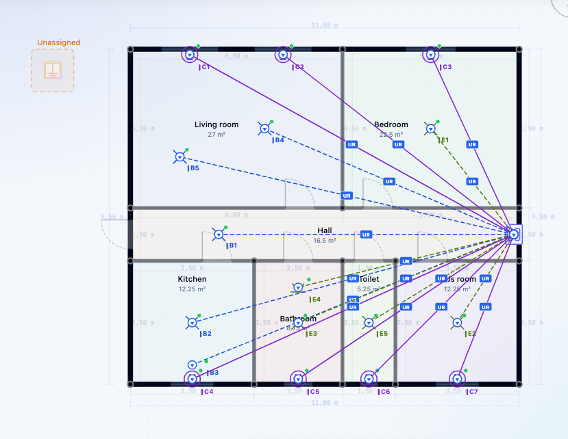
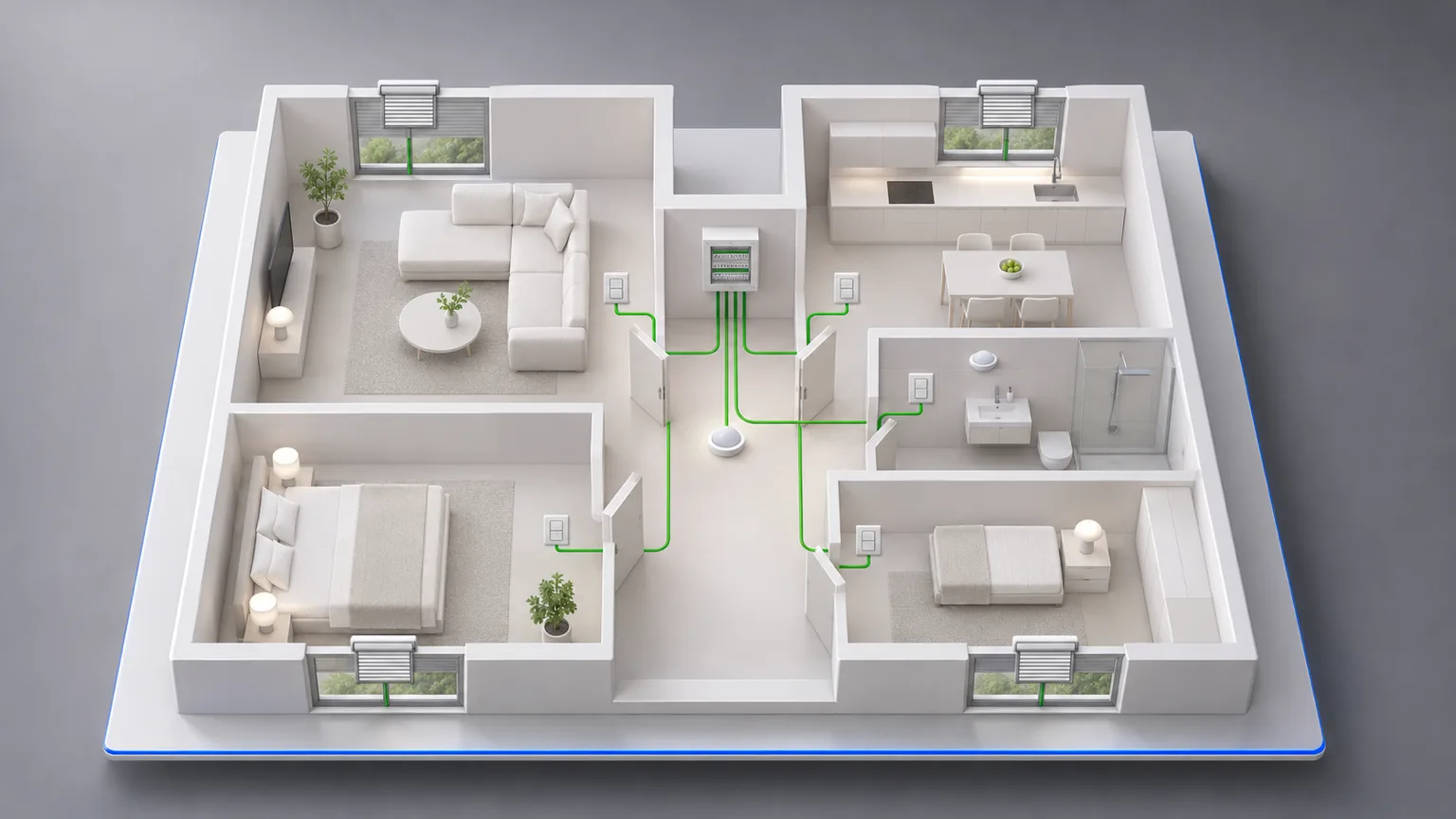
The apartment is fictitious: 11 × 9.5 m, one floor, seven rooms around a hall. Every room has a push button at the door, each of the seven windows an electric shutter. The hall and the bathroom also get a motion detector. The living room and the bedroom have dimmable lighting. The planning uses KNX.
| Room | Lights | Shutters | Control point | Detector |
|---|---|---|---|---|
| Living room | Ceiling light (dimmable), pendant (dimmable) | 2 | Quadruple push button | – |
| Bedroom | Ceiling light (dimmable) | 1 | Double push button | – |
| Hall | Ceiling light | – | Push button | yes |
| Kitchen | Ceiling light, LED strip worktop | 1 | Double push button | – |
| Bathroom | Ceiling light, mirror light | 1 | Double push button | yes |
| Toilet | Ceiling light | 1 | Push button | – |
| Kids room | Ceiling light | 1 | Double push button | – |
The 230 V side is already in place: three circuits for lighting and shutters behind a 300 mA RCD, the bathroom behind a 30 mA RCD.
How do I choose the automation system?
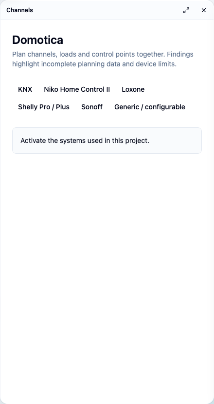
In the Smart home mode, the Channels panel opens. At the top is the Automation systems bar with KNX, Niko Home Control II, Loxone, Shelly Pro / Plus, Sonoff and Generic / configurable. One click activates the profile; a project can carry several systems. In the example apartment we choose KNX.
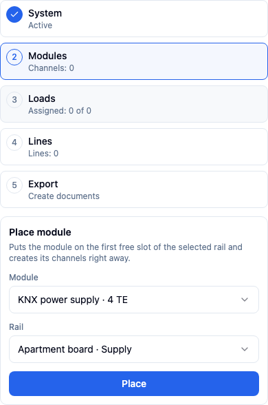
Next, the Domotica planning steps appear: System, Modules, Loads, Lines, Export. Each step shows its status and takes you with one click to the next open point.
How do I document the distribution board with modules, rails and terminals?
For 10 lights, 3 of them dimmable, and 7 shutters, five modules on two DIN rails are enough. We deliberately mix ABB i-bus types with vendor-neutral templates.
| Rail | Module | Manufacturer | Channels | used |
|---|---|---|---|---|
| KNX 1 | SV/S 30.640.5.1 power supply | ABB | – | – |
| KNX 1 | IPS/S 3.1.1 IP interface | ABB | – | – |
| KNX 1 | SA/S 12.16.2.2 switch actuator | ABB | 12 | 7 |
| KNX 2 | Shutter actuator 8× | vendor-neutral | 8 | 7 |
| KNX 2 | Dimming actuator 4× | vendor-neutral | 4 | 3 |
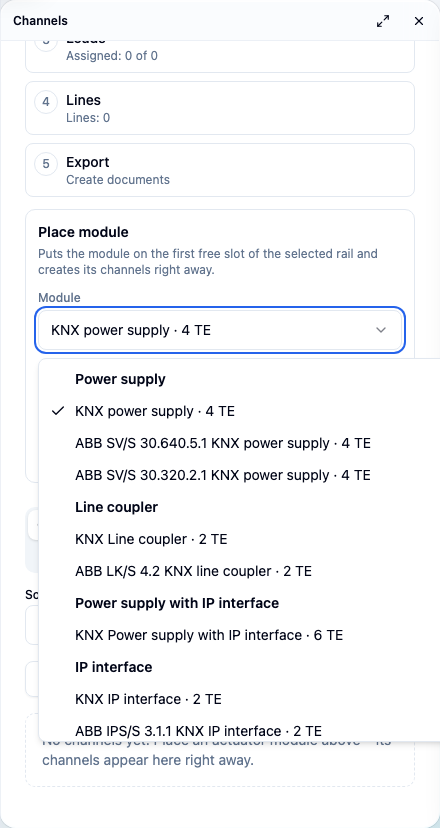
Below the planning steps you open Place module, choose module and rail and click Place. PlanElec puts the module in the first free slot, creates its channels and assigns it to the default line. The list groups the templates by family.
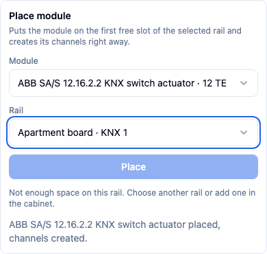
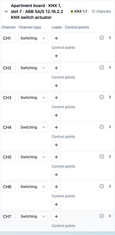
Right after placing, the switch actuator appears with its twelve channels in the channel table, still without loads.
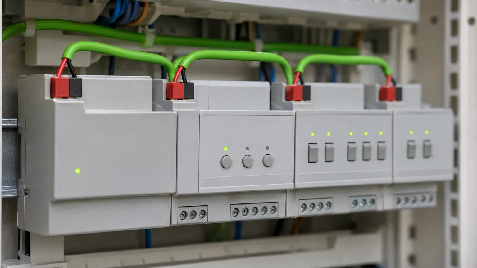
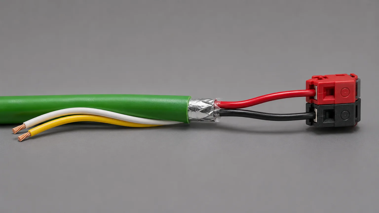
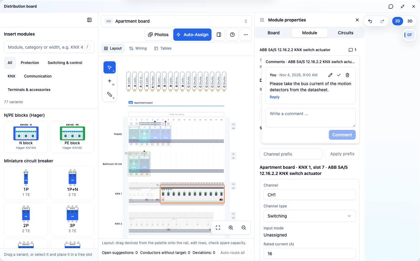
In the distribution board editor the modules sit on their rails, together with the main switch, RCDs and circuit breakers. That is also where you maintain terminal blocks and wiring. PlanElec shows the ABB types in the manufacturer's style, with a red and black bus terminal.
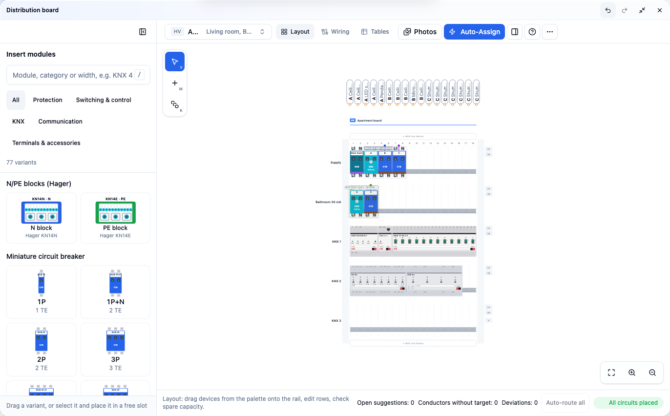
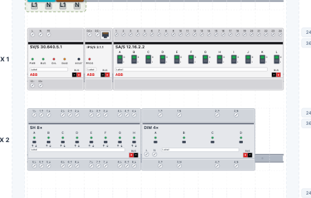
ABB i-bus or vendor-neutral?
Both work in the same project. PlanElec lists 15 ABB i-bus modules with order numbers: SA/S switch actuators, JRA/S blind actuators, UD/S dimming actuators, BE/S binary inputs, the VAA/S valve drive actuator, SV/S power supplies, the LK/S line coupler, the IPS/S IP interface and the IPR/S IP router. In the catalogue you filter the KNX group by manufacturer. For the other systems, vendor-neutral templates are available.
| Route | Advantage | What to watch |
|---|---|---|
| ABB i-bus type | Order number, bus current from manufacturer data, shown in the device's style | Check the datasheet before ordering |
| Vendor-neutral | Free for any brand, quick for early planning | Enter channel rating and bus current yourself |
ABB is a trademark of the ABB Group. PlanElec is not an ABB partner and uses no ABB or KNX logos.
How do I connect push buttons and motion detectors to the channels?
You place push buttons and detectors on the floor plan from the Control points & sensors catalogue: a push button, double push button or quadruple push button by the door, the motion detector on the ceiling. Bus control points join the line of their system without a further step.
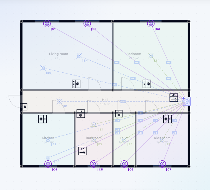
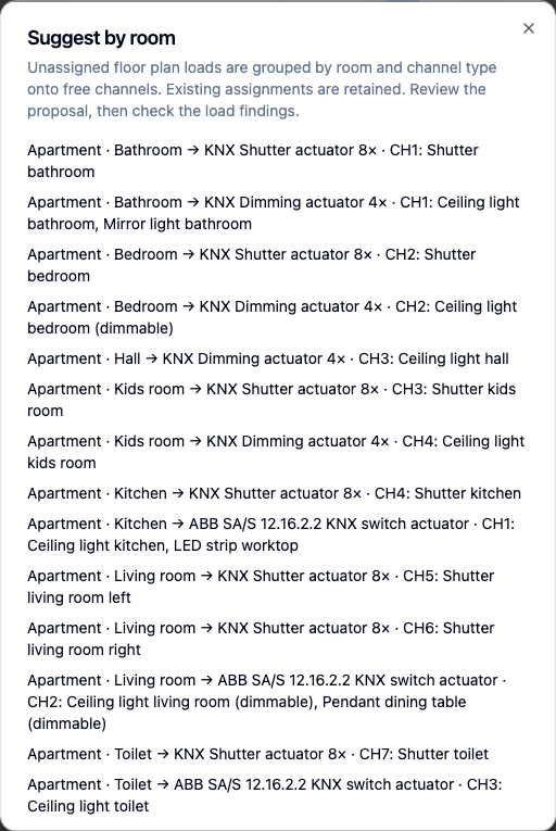
In the channel matrix you connect every channel to its load and its control point: + in the Loads column, + in the Control points column. Suggest by room proposes a distribution by room and channel type; existing assignments are kept.
What does the channel plan for the board door show?
Every channel sits on one row with channel type, load, room, control points, terminal, protective device and Line / PA; the line appears in its colour, for example “KNX 1.1”. Room and protective device come from the project; you do not enter them twice. CH1 "Ceiling light hall" has two control points: the push button and the motion detector. Exactly these rows become the channel plan that you stick on the board door as A4 landscape or edit further as CSV.
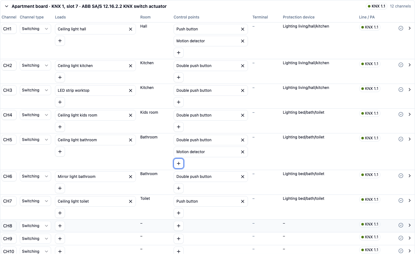
On the right of each row is the channel's finding. For the vendor-neutral dimming actuator PlanElec reports "The channel rated current is unknown": the template does not know the rating of the actual device. Other findings are loads assigned twice, loads without a protective device, an unsuitable channel type and overload.
| Finding | Meaning | What you do |
|---|---|---|
| Channel rating unknown | The channel has no rated current from template or input | Enter the value from the datasheet |
| Load unknown | The light has no power rating | Add the power at the device |
| Duplicate load | One load hangs on two channels | Remove one assignment |
| Protective device missing | The supply path of the load has no circuit breaker | Check the circuit in the diagram |
| Overload | Sum of loads above the channel rating | Spread the loads or choose another channel |
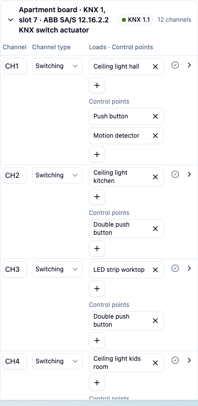
In the narrow dock next to the floor plan the table stays readable: control points move below the loads, and the line sits at the module.
Is one bus line enough for the apartment?
Yes, with plenty of headroom. In the Lines view all bus devices sit on line 1.1 in area 1. The power supply module is the ABB SV/S 30.640.5.1, the supply capacity 640 mA.
| Figure | Value in the example apartment | Limit |
|---|---|---|
| Bus devices | 13 | 64 per line |
| Bus current | 132 mA, of which 11 devices with an estimate | 640 mA |
| Line coupler | none needed | from the second line |
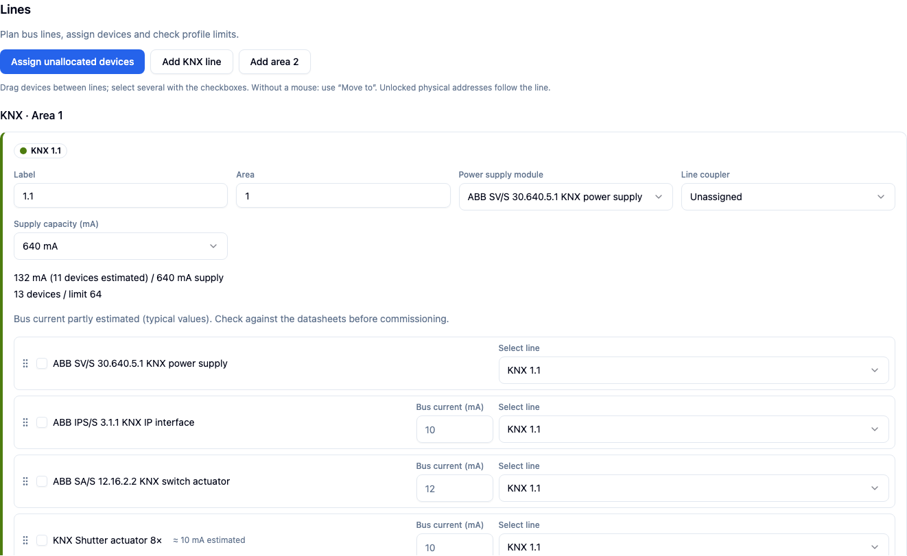
You move devices between lines by dragging, several at once via the checkboxes; without a mouse via Move to. Add area 2 opens another area. Unlocked physical addresses follow the line. Each line has its own colour and carries its address as its name, for example “KNX 1.1”.
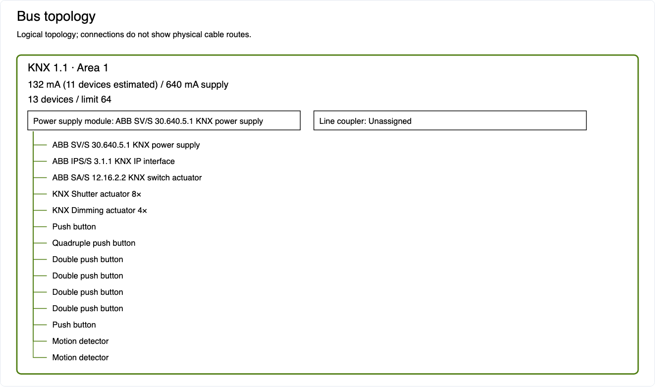
Bus current you do not enter is set to typical values and marked "estimated". For the ABB types the values come from manufacturer data, for the vendor-neutral templates and the control points they are estimates. Before commissioning you compare them with the datasheets. The topology shows the line as a logical picture; you draw the bus cable on the floor plan with Route bus.
How do I set functions and scenes per room?
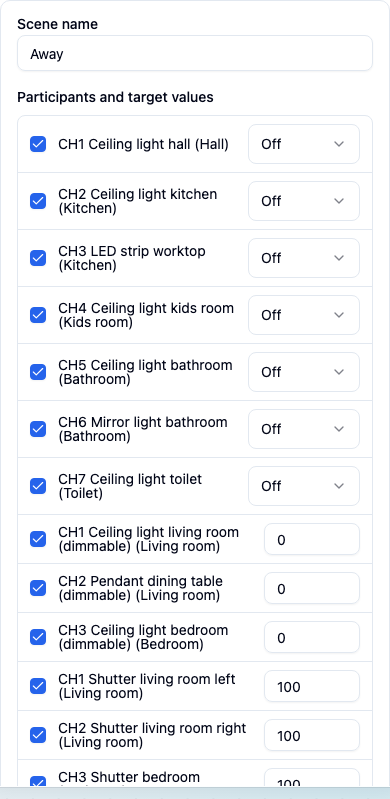
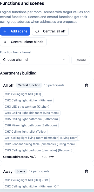
In the Functions view, Add scene creates a scene with target values. For "Away", all lights go off and all seven shutters go to 100 %. Central: all off and Central: close blinds create the two usual central functions in one click. The functions appear in the functions by room.
Which documents are produced for installation, handover and inspection?
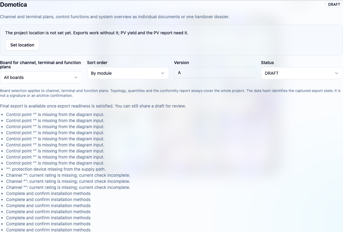
In Export mode, section Domotica, you choose distribution board, sort order, version and status. Every document has a preview and PDF, the channel and terminal plans also CSV, the topology SVG. Download Domotica dossier bundles everything behind one cover page. Draft carries a watermark and works with open data too; Final requires export readiness, and the interface names the open points.
| For whom | Document |
|---|---|
| Inspection | Single-line diagram with bus power supply, actuators and push buttons; situation plan |
| Electrician on site | Channel plan as board-door sheet, terminal plan, quantities |
| System integrator | Channel plan as CSV, functions by room, topology |
| Client | Functions by room, smart home dossier |
What of this belongs on the single-line diagram and the situation plan under the Belgian AREI/RGIE (the national electrical installation regulations) is explained in Home automation and KNX in the electrical installation.
How do I coordinate the project in the team?
Comments are attached directly to the object. In the distribution board you select the switch actuator and write a comment in Module properties, for example: Please take the bus current of the motion detectors from the datasheet.
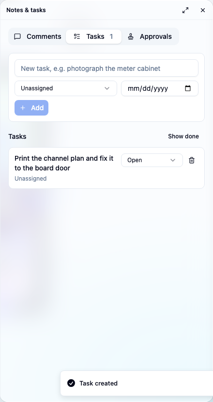
In the Notes & tasks panel you hand out tasks, for example to the electrician on site. Approvals of archived documents run through the same area.
What does KNX add: addresses and files for ETS?
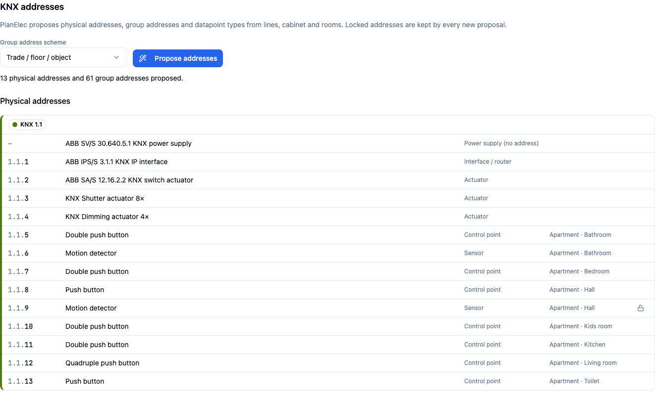
For KNX, PlanElec also proposes addresses. In the Addresses view you choose the Group address scheme and click Propose addresses. In the example apartment one step creates 13 physical addresses and 61 group addresses.
| Device | Physical address |
|---|---|
| ABB SV/S 30.640.5.1 | none (power supply) |
| ABB IPS/S 3.1.1 | 1.1.1 |
| ABB SA/S 12.16.2.2 | 1.1.2 |
| Shutter actuator 8× | 1.1.3 |
| Dimming actuator 4× | 1.1.4 |
| Push buttons and motion detectors | from 1.1.5, by room |
Group addresses have three levels. In the default scheme Trade / floor / object the main group is the trade, the middle group the floor and the sub group the running object; Floor / trade / object is the alternative.
| Main group | Trade | Example in the apartment | DPT |
|---|---|---|---|
| 1 | Lighting | 1/1/1 Hall ceiling light switching, 1/1/2 status | 1.001 |
| 2 | Dimming | Living room ceiling light: switching, dimming, value | 1.001, 3.007, 5.001 |
| 3 | Blinds | Kitchen shutter: up/down, stop, position | 1.008, 1.007, 5.001 |
| 5 | Inputs | Motion detectors hall and bathroom: switching, brightness | 1.001, 9.004 |
| 6 | Scenes | Scene "Away" | 17.001 |
| 7 | Central | "All off", "Close blinds" | 1.001, 1.008 |
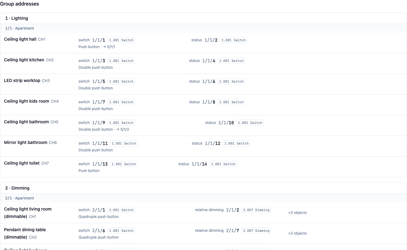
A push button gets no group address of its own; every key refers to the group address of its channel. The motion detector has its own switching object and a brightness object. Spare channels stay without a group address. Each row shows a channel with the name of its load; further objects appear as “+3 objects”. Clicking an address opens the input field; changed and locked addresses are kept by every further proposal, and the lock appears on locked addresses and on hover.
For this, Export has the ETS preparation box. It does not depend on the dossier approval.

| File | Content |
|---|---|
| Group addresses CSV (ETS) | Three-level format "3/1", main, middle and sub group, DPT as DPST-x-y |
| Group addresses XML (ETS) | Group addresses in the XML schema http://knx.org/xml/ga-export/01 |
| Physical address list CSV | Line, address, device, kind, room as a working list |
In the description of every group address PlanElec writes which keys, detectors and scene members use it. Devices, parameters and links are created in ETS. The files follow the ETS format; we have not tested an import against a particular ETS version and do not promise one.
Where are the limits?
| PlanElec | Manufacturer software, installation or inspection |
|---|---|
| Planning and documentation of board, channels, terminals, lines | Programming the devices, parameters, logic |
| Channel, terminal and function plans, topology, dossier | Wiring on site, single-conductor wiring plan |
| Bus budget with entered and estimated values | Measurement, bus diagnostics, commissioning |
| Logical lines and bus cable on the floor plan | Surveyed cable routes, insulation testing |
| KNX only: address proposal and files in ETS format | ETS project file (.knxproj), links to communication objects |
| Planning findings and the project's AREI self-check | Acceptance by the approved inspection body |
Frequently asked questions
Does this work without KNX?
Yes. Distribution board, channel plan, terminal plan, functions by room, dossier and collaboration apply equally to Niko Home Control II, Loxone, Shelly, Sonoff and vendor-neutral planning; lines and their limits follow the respective profile. Only the addresses and the files for ETS are KNX-specific.
Can I stick the channel plan on the board door?
Yes. The channel plan is meant as an A4 landscape PDF, sorted by module, circuit breaker, room or terminal. As CSV you keep editing it.
What is the difference between draft and final?
A draft carries a watermark and also works with open data. Final requires export readiness; the interface names the open points. A final document is not an official certificate of conformity either.
Do I need ABB modules?
No. Vendor-neutral templates work for any brand. The ABB types come with order numbers and bus current from manufacturer data.
Does PlanElec create an ETS project?
No. For KNX, PlanElec exports group addresses and physical addresses as files in ETS format. You create the ETS project, the devices and their links in ETS.
Where do I find the guide?
In the help centre under Plan and document a smart home installation: step by step with KNX. In the Studio, the Smart home tour in the learning center shows the same path in about three minutes.