Automatic planning
Edit switch chains, circuits and cable routes
Keep lighting control, circuit assignment and the physical cable path separate, and use the appropriate tool for each step.
 AuthorStephan Behm
These three tools answer different questions: which switch controls which light? Which circuit supplies which device? Where does the cable physically run? Edit them in sequence so that the plan remains technically traceable.
Link switches and lights as a chain
Choose Switch chain in the floor plan. It links switches and the lights they control in a logical order. PlanElec can propose a chain for free switches and lights in one room; always check the proposal against the intended controls.
For a manual chain, deliberately select the participating devices. A valid chain includes at least one switch and one light. A device cannot belong to multiple switch chains at once. Across several floors, the chain remains project-wide; each floor shows only its local sections and continuation markers.
Switching function and pole count are separate settings. The application can derive a one-way, two-way or intermediate switching function from the chain; you choose the pole count explicitly. A double switch is one physical device with two separate channels: deliberately assign each light to channel A or B.
Assign devices to an existing circuit
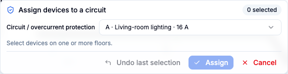
Choose Assign circuit. In the panel, first select the target circuit or its MCB, then select devices, including through the floor selector. Done applies the selection together.
Devices that are not yet linked are created as consumers under the selected MCB and linked to their floor-plan symbol. When a device already belongs to another MCB, the application asks for explicit confirmation before moving it. Cancelling changes no project data; you can undo the entire confirmation in one step.
Circuit assignment describes electrical membership. It does not yet define the physical path through walls, shafts or floors.
Plan and refine the cable route
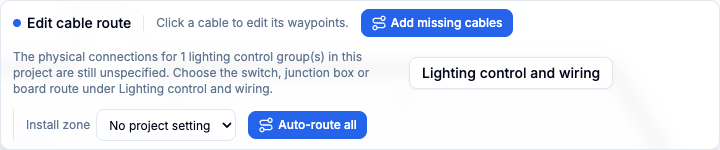
In the situation plan, open Linking & cabling → Cable route. When cables exist in the topology, use Auto-route all for the active floor or select a cable and choose Auto-route. The automatic route follows drawn walls where possible; check it against the intended installation.
Select a cable line to edit it manually. Click a segment to add a waypoint and drag it immediately; double-click to remove a waypoint. Escape clears the selection or exits the mode. The displayed length is used by material lists, voltage-drop calculation and exports, so check every exceptional route.
For a cable between floors, explicitly select an existing stair, shaft or riser in the cable-route panel. PlanElec does not invent a vertical connection. If a required connector or reliable heights are missing, the route remains incomplete instead of showing a misleading length.
Final check
- Test the switch chain against the intended controls, not only spatial proximity.
- Check each device's circuit, protective device and topology.
- Check cable route and length against the planned installation path.
- Treat automatic proposals as editable planning assistance, not approval for construction.
You can then continue checking the distribution board and single-line diagram, and run the supported self-check.
Important for electrical planning
These guides explain the software workflow. Have the design, installation and documents reviewed by a qualified electrician where needed; only an accredited inspection body performs the official inspection.
Continue reading
Getting started: from project to first export
Build a PlanElec project step by step: project details, floor plan, rooms, electrical devices, distribution board, diagram, and export.
Using and reviewing automatic planning
Use PlanElec proposals for devices, switch chains, cable routes, circuits, phases, and the distribution board without skipping technical review.