Getting started
Getting started: from project to first export
Build a PlanElec project step by step: project details, floor plan, rooms, electrical devices, distribution board, diagram, and export.
 AuthorStephan Behm
PlanElec uses one project model for the floor plan, electrical topology, distribution board, and documents. A fixed order therefore works best: capture the spaces and devices first, review the electrical structure next, and export only after that.
Using PlanElec as an owner or self-builder? Have all decisions and documents reviewed by a qualified electrician before installation and inspection.
1. Create the project
Choose Create project in the project overview. You can start with the guided workflow, a localized project template, or an empty project.
Enter at least a recognizable project name. You can add these project details later:
- customer and contact details;
- installation address;
- installer and optional logo;
- EAN, installation type, and current type;
- recognized inspection body and project notes.
PlanElec reuses these details in title blocks, the self-check report, and the working dossier. Missing details do not prevent you from trying the workflow or downloading drafts, but review them before sharing documents.
2. Draw the floor plan and build the situation plan
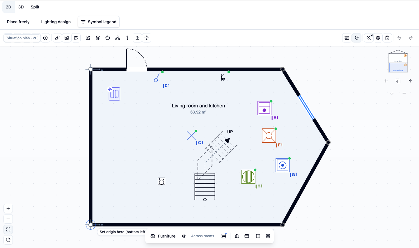
Create a floor first. Then draw the exterior and interior walls with the polygon, rectangle, or line tool. Closed wall areas are detected as rooms; give each room a clear name, such as Kitchen or Bedroom 1.
If you already have a plan image, use it as a reference. Calibrate it with a known measurement before placing things precisely. The image is an underlay: walls, openings, and electrical points remain separate project data.
Next, place doors, windows, stairs, and electrical symbols in their real locations. This floor plan becomes the basis for the situation plan PDF.
Practical check:
- Are all floors and rooms present and named?
- Are sockets, switches, lighting points, and fixed appliances in the right room?
- Is the distribution board positioned on the plan?
- Are bathroom zones and special appliances recorded correctly where relevant?
3. Place and connect electrical devices
Open the symbol palette and place the electrical points you need. Helpers can propose sockets, lighting, standard equipment, or a spotlight grid. Review and edit those proposals: they do not decide the required quantities or final positions for you.
Connect switches and lights in switch chains. PlanElec can propose a chain for unassigned switches and lights in the same room; you can still edit the sequence manually.
A floor-plan symbol and an electrical node belong together, but they are not the same object. Review the unconnected-components panel. Without valid topology, a device cannot reliably appear in a circuit, cable, or material list.
Read Using automatic planning for details about proposals, cables, and circuits.
4. Review the electrical topology and distribution board
Use automatic circuit assignment as a starting proposal. PlanElec groups standard devices, creates dedicated protection for special appliances where required, and can distribute loads across phases. Review the preview before applying the assignment.
Then open the distribution board editor. Auto-fill places existing main switches, RCDs, and circuit breakers on DIN rails while reserving spare capacity. Review:
- the protection chain and assigned devices;
- cable type, cross-section, and route;
- RCD groups and circuit counts;
- phase allocation for a multiphase installation;
- spare module positions and the actual board dimensions.
Every automatic result remains editable. A proposal is not an engineering decision or a material order.
5. Review the single-line diagram and self-check
The single-line diagram is generated from the same electrical topology. Check circuit names, protection devices, cable data, connections, and symbols. Resolve the errors and warnings PlanElec can identify from the available project data.
The AREI/RGIE self-check covers a documented subset of rules that software can evaluate from that data. A clean run only means that no error was found within those supported rules. Measurements, on-site conditions, and rules that are not modeled remain outside its scope.
PlanElec therefore does not issue a certificate of conformity and does not replace an official inspection by a recognized inspection body.

6. Export and review the documents
In Export, you can generate the single-line diagram and situation plan as PDFs. The self-check report and circuit, cable, and material lists are also available centrally; the detailed lists are still part of the pilot workflow.
You can combine selected documents into a working dossier with a cover, document index, and continuous page numbering. Review every page and the project metadata before sharing it.
See Exporting documents for the full list, statuses, and limitations.
A useful first milestone
Your first project is well structured when:
- rooms and electrical points are shown on the situation plan;
- all relevant points are linked to the electrical topology;
- circuits, cables, and board layout have been reviewed;
- the single-line diagram is readable;
- the self-check has run and you understand the remaining findings;
- exported documents have been checked visually and technically.
Ready to begin? Create a free Early Access account.
Continue planning the electrical installation
You can also assign existing devices to circuits in Installation, follow their protection paths and form distribution boards after a preview. Enclosures and module positions can remain open initially. The suggested sequence is guidance; existing projects and other valid starting points remain supported.
Important for electrical planning
These guides explain the software workflow. Have the design, installation and documents reviewed by a qualified electrician where needed; only an accredited inspection body performs the official inspection.
Continue reading
Using and reviewing automatic planning
Use PlanElec proposals for devices, switch chains, cable routes, circuits, phases, and the distribution board without skipping technical review.
Exporting documents and assembling a working dossier
See which PDFs PlanElec creates, which outputs are available or in pilot, and what to review before sharing or inspection.