Getting started
Plan an installation and form distribution boards
Assign existing floor-plan devices, check protection paths and develop an electrical plan into distribution boards, cabinet layouts and a single-line diagram.
 AuthorStephan Behm
In Installation, you plan which protective device supplies each circuit and its consumers. You use devices already placed in the floor plan. An enclosure and fixed module positions are not required yet. You can then form distribution boards, detail their cabinet layouts and review the resulting single-line diagram.
This guide follows one fictional home in the same project file. Its screenshots show real views of that example in the application. The sequence provides a starting point; existing projects and other valid planning approaches remain supported. A planning view or an exported draft does not establish electrical safety.
Quick start: from distribution board to topology
- Place loads and a distribution board on the floor plan.
- Select the board and Complete installation automatically. The same action is available in Installation.
- Review the target board, new circuits, protection devices and required space. Apply proposal adds the plan and opens the board’s topology.
- Open the cabinet view to inspect the prepared layout.
All unassigned loads without an assignment to another board are included. Existing circuits, cable data and module positions are preserved. An unconfigured cabinet receives an enclosure proposal; insufficient space in an existing enclosure is reported. Devices that require manual planning and missing feeder data remain open. One undo step reverses the operation. If the project changes, review the refreshed proposal before applying it. The preview lists every planned assignment by room with circuit, protection device and RCD. An empty circuit whose name matches the load is reused instead of adding another protection device.
The following sections explain manual editing and installation review.
What is each view for?
| View | What you plan here |
|---|---|
| Floor plan / situation plan | Device positions and physical cable routes |
| Installation | Supply, protection paths, circuits and board boundaries |
| Cabinet | Concrete devices, enclosure, rows and module positions |
| Single-line diagram | Document representation of the same electrical installation |
| Export | Documents from the saved project version with a visible review status |
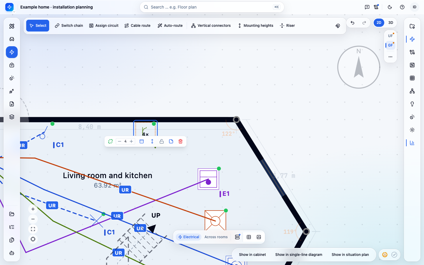
Assign an existing floor-plan device
- Place devices in the floor plan or open an existing project. See place and connect electrical symbols.
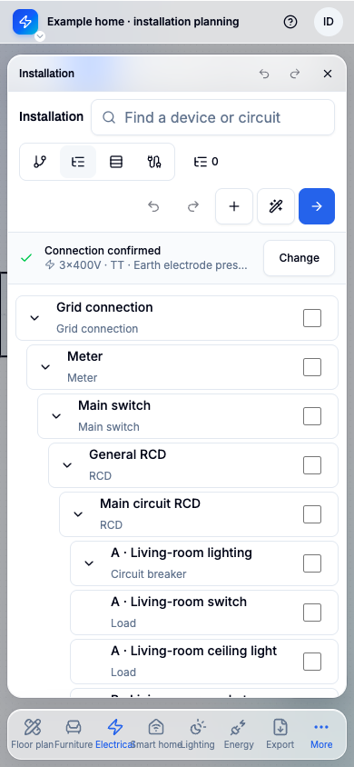
- Open Installation, search for the device and select it in the tree or graphical view.
- Click Assign circuit, choose the existing target circuit and confirm.
- Check the displayed protection path. The floor-plan link takes you to the associated symbol.
This assigns the same device. Do not create another consumer just to see it in the diagram. In the example, the existing living-room socket receives its circuit assignment.
Move loads in the circuit list
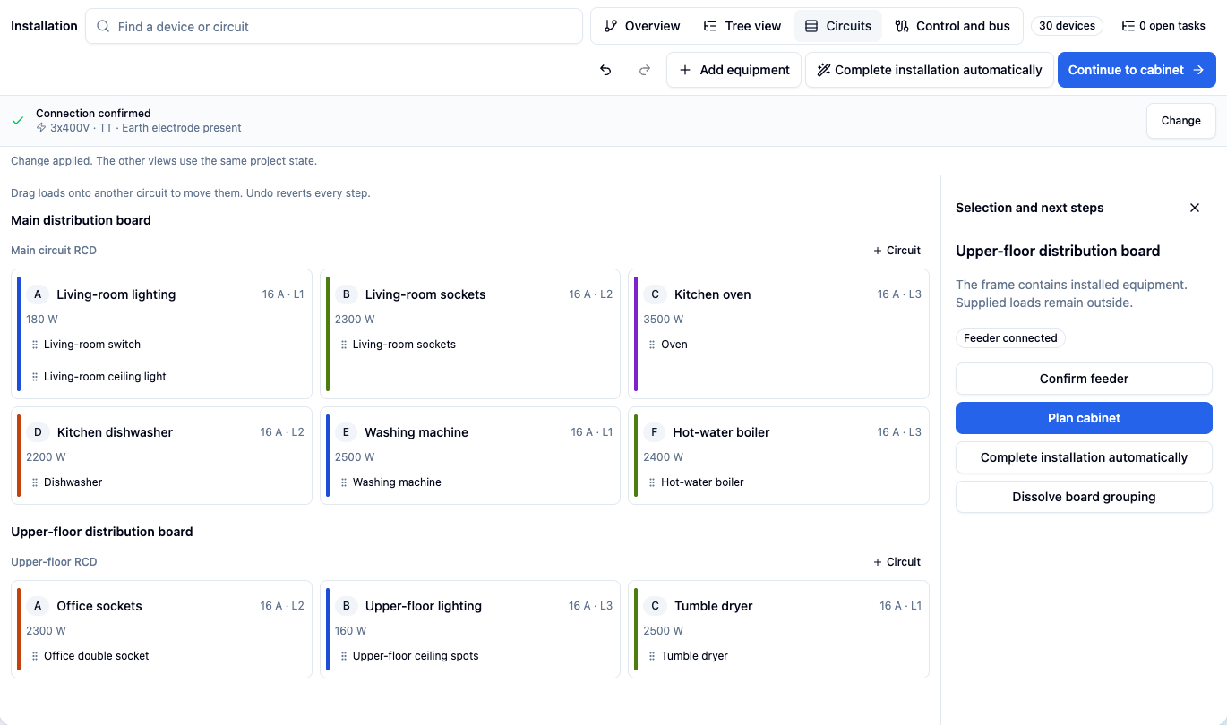
The Circuits view lists every final circuit by board and RCD, with its loads, the sum of the recorded power and the phase. Loads without a circuit are shown at the top.
- Open Installation and choose the Circuits view.
- Drag a load onto the target circuit. Its cables move with it.
- Undo reverts the step completely.
Only items connected directly to the circuit breaker can be moved; a junction box takes its loads with it. The room filter shows only circuits that supply the selected room. Without a mouse, select the load and use Assign circuit.
Resolve open tasks
With nothing selected, the side panel lists open tasks – one line per problem, not per device.
| Task | Solution in the side panel |
|---|---|
| Loads without a circuit | Assign automatically opens the automatic planning proposal |
| Board open: electrically connected but not assigned to a board | Form board opens the preview for the whole chain from its top device |
Below are actions for the whole installation. Balance phases spreads single-phase circuits more evenly across L1–L3 on a three-phase supply without moving module positions. Add missing cables creates only missing cables; existing cables and their data stay unchanged. Calculate cable routes fills in missing routes on the floor plan and leaves manually drawn routes unchanged.
Read the complete supply and protection path
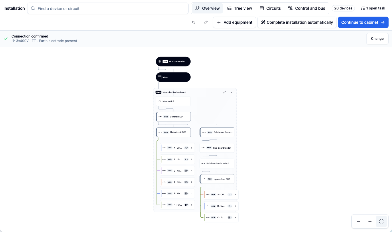
Return to the installation. The grid connection, meter, protective devices, circuits and consumers remain reachable together. Select a consumer to see its path back to the supply. Device references and circuit labels help you compare the floor plan and diagram.
Use search, expand/collapse and the tree view for larger projects. A collapsed branch still exists. Control relationships, switching functions and bus assignments are additional relationships; they must not be treated as arbitrary supply connections.
Continue without a chosen cabinet
An undecided board is a saveable draft state. Save and reload the project: the open assignment remains open instead of being silently attached to a main board.
| State | Next step |
|---|---|
| Not electrically assigned | Choose the supply or circuit |
| Electrically connected, board open | Plan a suitable physical group |
| Board chosen, layout open | Check the feeder and detail enclosure and modules |
| Modules placed | Review layout, electrical information and documents |
Form a distribution board from a selection
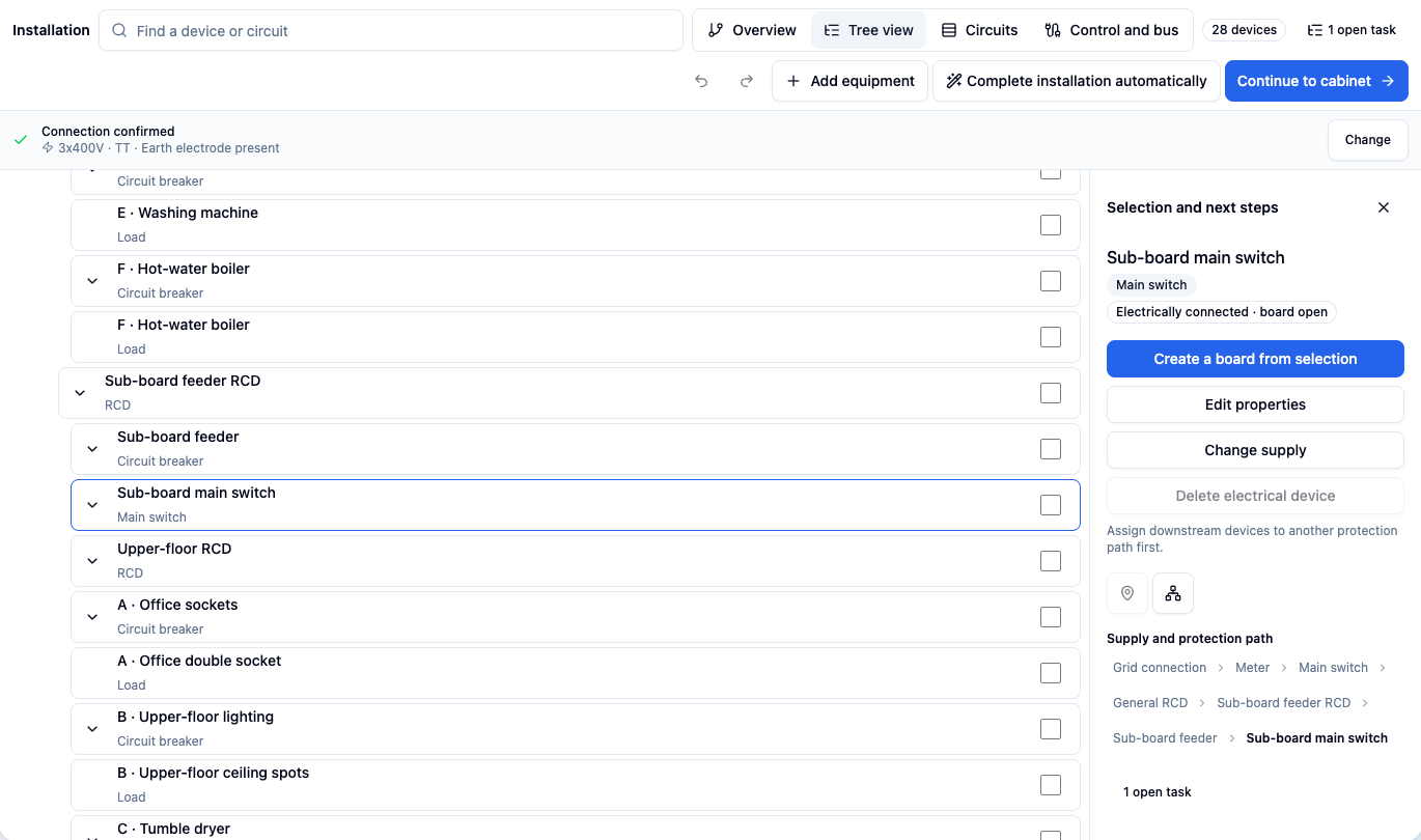
- Select related protective devices using individual tree checkboxes or multiple selection in the graphical view.
- Click Create a board from selection and give it a clear name.
- Read the preview: supply entry, modules, consumers outside the cabinet, existing board boundaries and affected placements.
- Confirm only a suitable selection. If the selection conflicts, the application explains why; adjust it before continuing.
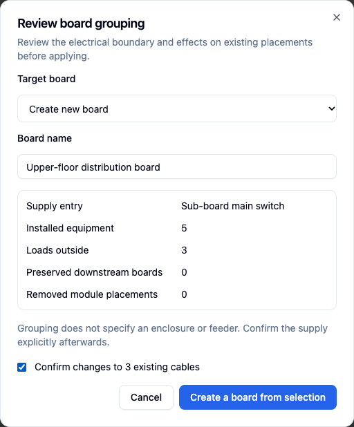
After confirmation, the protective devices belong to the new physical board. Its supplied sockets and lights remain outside the frame. Electrically downstream boards are not enclosures physically nested inside each other.
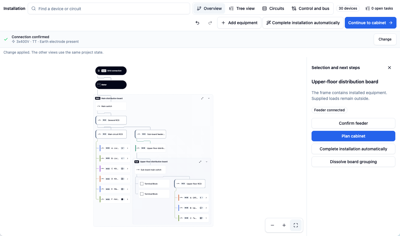
Next, check the feeder: select the actual upstream protective device and enter cable information such as conductor count, cross-section and length. Confirm that connection explicitly. Grouping invents neither a protective device nor a feeder cable. Radial planning requires one unambiguous upstream supply path; local sources such as PV are handled separately.
What do removal and deletion change?
| Action | Effect |
|---|---|
| Dissolve board grouping | Remove the physical group; retain electrical devices for planning |
| Remove module placement | Remove the row position; retain the electrical device |
| Delete an electrical device | Change the electrical object and its affected connections |
Read each preview or confirmation, then review the affected views. Related electrical changes can be followed with undo/redo.
Detail modules and enclosure
Open the cabinet from the selected distribution board. Existing devices are carried over and unplaced modules remain findable. Choose concrete modules, check their width in module units (TE) and plan the rows.
Enclosure planning shows the module requirement and uses your entered reserve and terminal/accessory allowance. Check mounting type, wiring space, heat dissipation and manufacturer conditions. With generic modules or missing information, the space requirement remains an estimate. A proposed enclosure is not approval for construction.
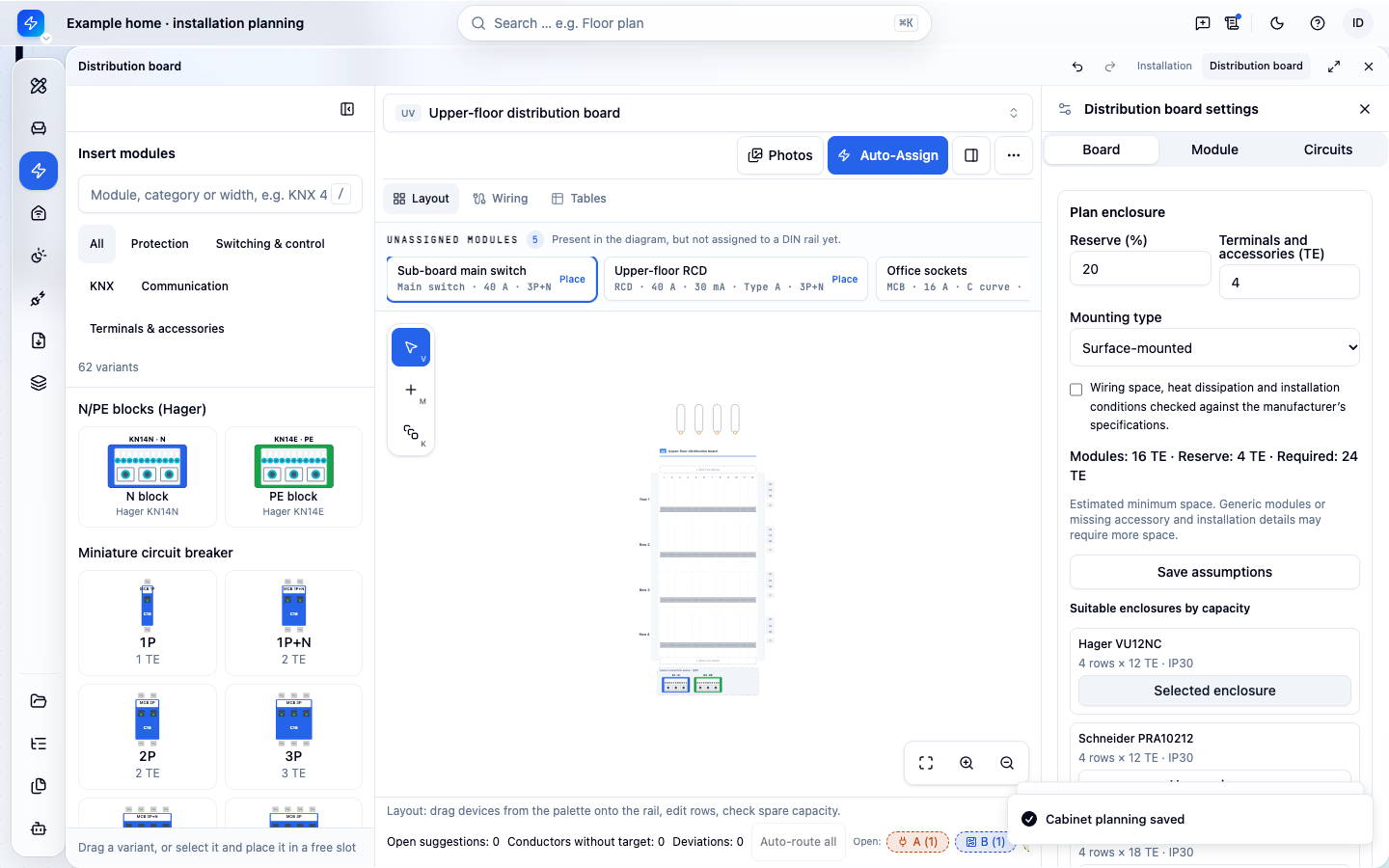
Review the single-line diagram and export documents
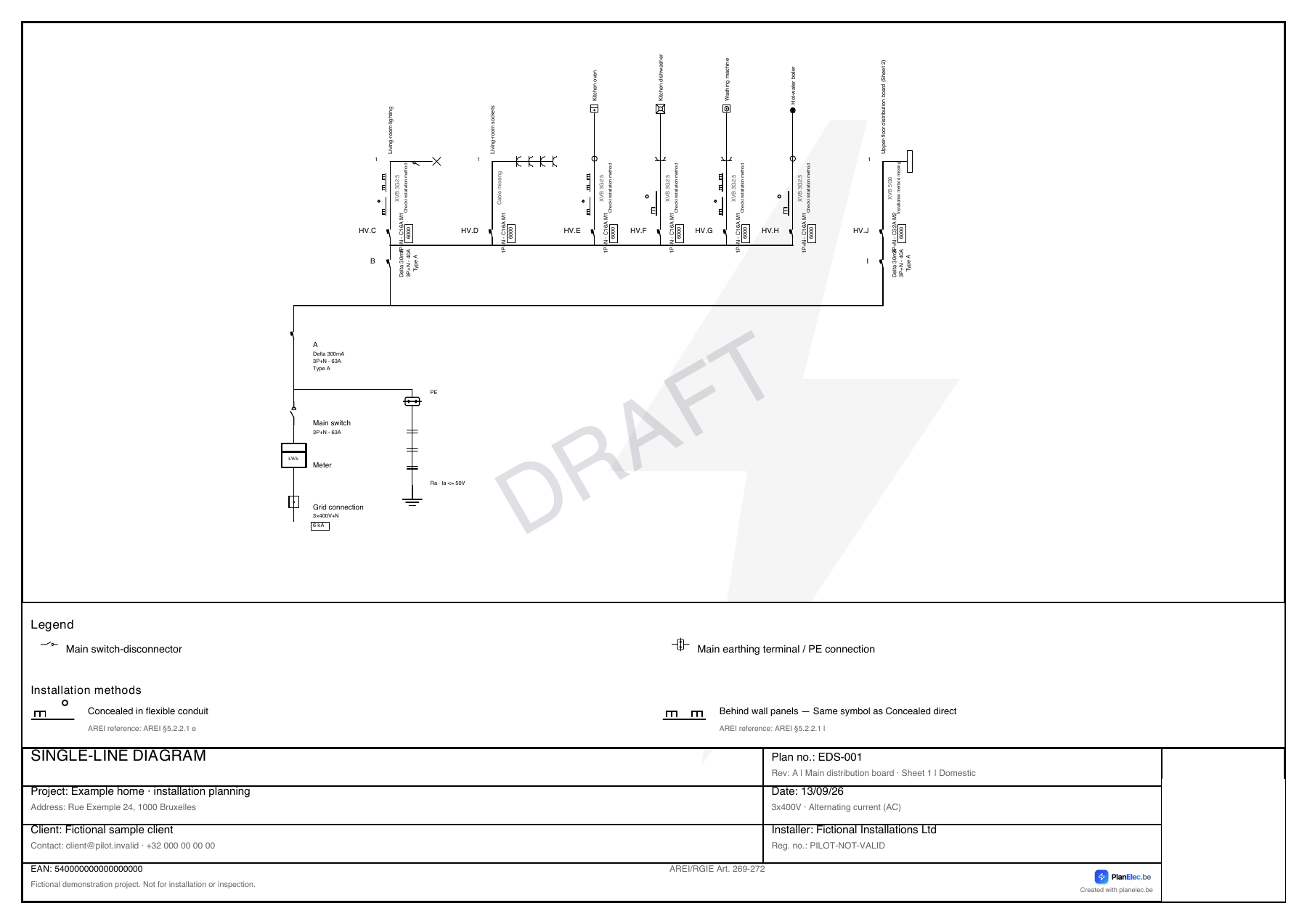
Open Single-line diagram. The same consumers, protective devices and boards appear in the document view. Check board-specific sheets and cross-references. The diagram is rendered from the project model; it is not a screenshot of the installation tree.
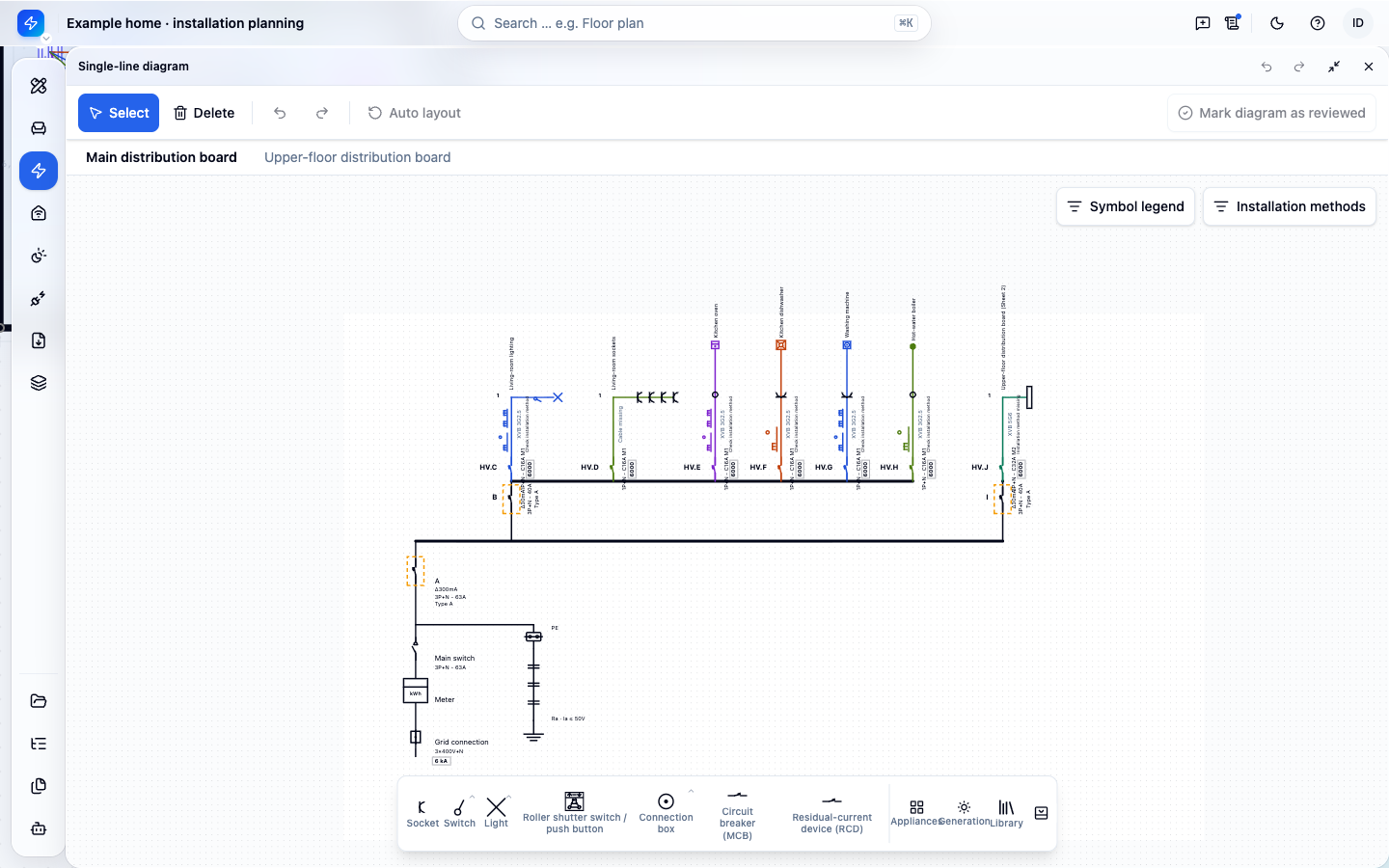
Switch to Export, check the saved version and choose the required documents. Open assignments, cable information and reviews remain visible. A download offered as a draft remains a draft. Producing documents does not replace professional review or the official inspection.
Read more: export documents and what the self-check verifies.
Work on a tablet, phone or with the keyboard
On narrow screens, the tree view takes priority. Use checkboxes and named actions for assignment and board grouping. Arrow keys move through the tree, Enter opens the selected item and Space selects an item for multiple selection.
Important for electrical planning
These guides explain the software workflow. Have the design, installation and documents reviewed by a qualified electrician where needed; only an accredited inspection body performs the official inspection.
Continue reading
Getting started: from project to first export
Build a PlanElec project step by step: project details, floor plan, rooms, electrical devices, distribution board, diagram, and export.
Using and reviewing automatic planning
Use PlanElec proposals for devices, switch chains, cable routes, circuits, phases, and the distribution board without skipping technical review.