Automatic planning
Using and reviewing automatic planning
Use PlanElec proposals for devices, switch chains, cable routes, circuits, phases, and the distribution board without skipping technical review.
 AuthorStephan Behm
PlanElec's automatic functions create editable proposals. They reduce repetitive work, but they cannot know which equipment will actually be installed, how a cable will run on site, or which product specifications your electrician will select.
Use the same pattern each time: create proposal → review preview → apply → check technically.
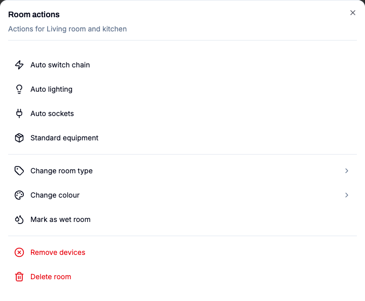
Propose devices and lighting points
The floor-plan editor includes helpers for automatic sockets, lighting, standard equipment, and spotlight grids. The proposals use the drawn rooms and geometry as their basis.
For a useful result:
- draw closed, correctly named rooms;
- set the required count or pattern where applicable;
- inspect the proposed positions;
- move, add, or remove points to match the real design;
- review special zones and fixed appliances separately.
PlanElec does not silently add every missing appliance. You remain responsible for the design brief and final placement.
Build switch chains automatically
PlanElec can propose a switch chain for unassigned switches and lighting points in the same room. It normally starts with the free switch closest to a door and then connects nearby free points.
Always verify which switch controls which light. Edit the sequence manually when the real control logic differs.
Generate cable specifications and routes
Once the electrical topology exists, PlanElec can create a cable segment for each parent-to-child connection. A real connection or junction box splits the connection into separate segments. A box that is only nearby is not silently inserted into the electrical path.
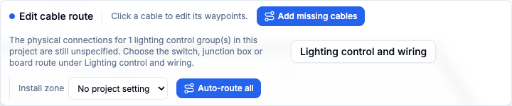
Automatic routing searches for a short route along the drawn walls on each floor. If the start and end are not connected through the same wall component, the router uses a direct fallback.
In the situation plan, open Linking & cabling → Cable route in the top toolbar.
After routing:
- check whether the route matches the intended installation;
- add or move waypoints where required;
- review cable type, cross-section, and installation method;
- enter a manual length when the calculated route does not represent reality closely enough.
The resulting length feeds the material list, voltage-drop calculation, and validation. It is a net length without an automatic waste or reserve factor.
Assign devices to circuits automatically
Automatic circuit assignment creates a proposal from the recorded devices and product rules. It supports decisions such as:
- grouping standard lighting and socket points by room;
- allowing no more than eight connection points on a standard circuit;
- creating dedicated breakers for appliances including hobs, ovens, washing machines, tumble dryers, dishwashers, boilers, heat pumps, and saunas;
- placing standard groups behind 30 mA RCDs;
- assigning an EV charger a separate 30 mA RCD and three-phase breaker; with documented built-in 6 mA DC detection PlanElec proposes external Type A, otherwise Type B;
- distributing assignments across boards in a multi-board project.
Review the preview before confirming it. Pay particular attention to mixed circuits, special appliances, existing manual assignments, and whether the defaults suit the actual project.
Balance loads across phases
For a three-phase or delta supply, PlanElec can distribute loads across L1, L2, and L3. The phase overview shows the calculated load on each phase and warns about a clear imbalance.
This remains a model calculation based on the entered loads. Real simultaneity, measurements, and network conditions require assessment outside the software.
Fill the distribution board automatically
Auto-fill places existing main switches, RCDs, and MCBs in free DIN-rail slots. Its default sequence is main RCD, group RCDs, and then circuit breakers. By default, it reserves about twenty percent of the rail capacity.
The distinction from circuit assignment matters:
- Circuit assignment creates and connects the electrical protection structure.
- Auto-fill arranges those existing modules physically in the board.
After auto-fill, review the board size, TE widths, spare capacity, protection chains, and connection paths. Explicit paths through connection boxes are preserved when the board is filled again.
Final review of an automatic proposal
After every automatic action, check:
- Completeness: are all real devices, boxes, and boards modeled?
- Topology: is each parent-to-child connection correct, with nothing left unconnected?
- Protection: do the RCD, MCB, pole configuration, and cable suit the application?
- Space: are routes and positions practical on site?
- Phases: is the allocation plausible for the entered loads?
- Documents: do the situation plan and single-line diagram remain readable?
The AREI/RGIE self-check helps with supported rules that can be evaluated from project data. It is not a declaration of conformity and does not replace an electrician's review or the official inspection.
Continue with Exporting documents.
Continue planning the electrical installation
You can also assign existing devices to circuits in Installation, follow their protection paths and form distribution boards after a preview. Enclosures and module positions can remain open initially. The suggested sequence is guidance; existing projects and other valid starting points remain supported.
Important for electrical planning
These guides explain the software workflow. Have the design, installation and documents reviewed by a qualified electrician where needed; only an accredited inspection body performs the official inspection.
Continue reading
Getting started: from project to first export
Build a PlanElec project step by step: project details, floor plan, rooms, electrical devices, distribution board, diagram, and export.
Exporting documents and assembling a working dossier
See which PDFs PlanElec creates, which outputs are available or in pilot, and what to review before sharing or inspection.