Creating a Single-Line Diagram: Step by Step under AREI/RGIE
How to create and draw a reviewable Belgian single-line diagram: required information, Table 2.23 symbols, an example, solar PV, circuit references and PDF export with PlanElec.
 AuthorStephan Behm
You create a single-line diagram in four steps: record the consumers room by room, define protective devices and circuits, check the topology with unambiguous references, and export the diagram together with the situation plan as a PDF. AREI/RGIE sets out content and referencing in Section 3.1.2; the symbols are in Table 2.23. In PlanElec, the diagram is derived directly from your project model: you add the technical data and check the result.
Want to see an example first? Open the fictional PDF dossier. It shows the real export structure with sample data; for your own installation, you enter the real values.
What is a single-line diagram?
A single-line diagram (Dutch: eendraadschema, French: schéma unifilaire, German: Eindrahtschema) is a simplified electrical schematic that shows the structure of your entire installation with standardised symbols. A wiring diagram draws every conductor; the single-line diagram shows each circuit as one line and labels it with the number of conductors, cross-section and protection.
For every new domestic installation and every substantial modification or extension, the person responsible for carrying out the work prepares the single-line diagram and the situation plan, called a position plan in the regulation (AREI/RGIE 3.1.2.1 a). Existing installations and non-substantial changes follow their own, narrower rules. At the inspection, the approved inspection body assesses the actual dossier and the installed work.
What do you need the single-line diagram for?
| Purpose | What the diagram does |
|---|---|
| Inspection (keuring) | required document for new installations and substantial modifications or extensions (3.1.2.1 a); when conformity is established, the responsible person and the approved body sign diagram and plan |
| Safety overview | shows every protective device and its order from the supply point to the consumer |
| Maintenance and faults | any electrician finds circuits and components by letter and number |
| Later changes | the basis for planning and documenting extensions |
| Sale of a dwelling | diagram and plan belong to the installation file you hand to the buyer (9.1.2); if they are missing at the sale inspection of an old installation (before 1981), the approved body records only a short description and a rough sketch and notes their absence as an infringement (8.4.2.2 d) |
Important: the documents show the current state and are available on site (3.1.2.1 d). For a non-substantial change, a dated and signed short description is enough instead of a new diagram; you still update the situation plan.
Single-line diagram symbols: what AREI/RGIE Table 2.23 covers
Table 2.23 in Chapter 2.13 is the official, non-exhaustive symbol list for the single-line diagram and the situation plan. If a symbol is missing, you use another unambiguous sign and define it in the legend (3.1.2.1 a). The table is organised in groups:
| Group | Examples from Table 2.23 |
|---|---|
| A. General | direct current, alternating current, single-phase and three-phase AC |
| B. Switchgear | distribution board, junction and branch box, service connection box, earthing switch |
| C. Wiring | number of conductors and installation method (embedded, surface, in conduit, underground), e.g. three-core XVB-Cca 2.5 mm² surface-mounted |
| D. Protective devices | fuse (e.g. 16 A gG), circuit breaker with release letters M, O and Δ, residual-current device (example 300 mA, type A, 40 A), earth electrode |
| E. Switches | switch, two-way and intermediate switch, series switch, dimmer, push button, time-delay switch, remote-control switch, thermostat, motion detector |
| F. Socket outlets | socket outlet, multiple socket, splash-proof socket, socket with earth contact, child-protected socket, data socket |
| G. Appliances | lighting point, wall light, cooker and hob, washing machine, dryer, dishwasher, water heater, motor, EV charger, kWh meter |
| H. Sources | transformer, solar cell, inverter, DC/DC converter |
| J. Home automation | control unit with base symbol and control type (push button, wireless, programmed, sensor) |
The table has no dedicated symbol for surge protection or equipotential bonding. You draw such components with an unambiguous sign defined in the legend. The full overview is in AREI electrical symbols; switch types are covered in Two-way and intermediate switching in the single-line diagram.
Drawing a single-line diagram step by step with PlanElec
Step 1: Record the installation
- Open PlanElec and create a new project.
- Create the rooms of your building: living room, kitchen, bedrooms, bathroom, utility room.
- Place the electrical points in each room:
- socket outlets (single, multiple, splash-proof)
- lighting points and their switches
- fixed appliances such as oven, hob or water heater
- dedicated circuits for an EV charger, heat pump or PV system
If you already have a plan as a PDF or scan, PlanElec recognises walls, rooms and supported device symbols in it as an editable proposal. You give the PlanElec Assistant instructions in your own words, for example "Place three sockets in the kitchen".
Step 2: Define protective devices
PlanElec proposes circuits and protective devices as a starting point. The minimum AREI/RGIE rules for domestic installations are mainly in Subsections 5.3.5.1 b (main switch) and 4.2.4.3 b (RCD protection):
| Protection | AREI/RGIE rule |
|---|---|
| Main switch-disconnector | in the main board; breaks all line conductors and, where applicable, the neutral simultaneously; at least 40 A |
| RCD at the supply point | at least one residual-current device of no more than 300 mA (at least Type A, at least 40 A); it additionally provides the isolating function |
| Additional RCD (≤ 30 mA) | required for socket outlets (except those for fixed appliances), lighting, rooms with a bath or shower, and washing machines, dryers and dishwashers; at most eight final circuits per device |
| Circuit breaker or fuse | matched to cross-section, installation method and load of the circuit |
| Surge protection | where your installation requires it |
Check every proposal against the equipment actually installed, its technical data and the complete sizing of the circuit. You set the type, rating and coordination of the RCDs for the actual protection chain.
Step 3: Check the topology
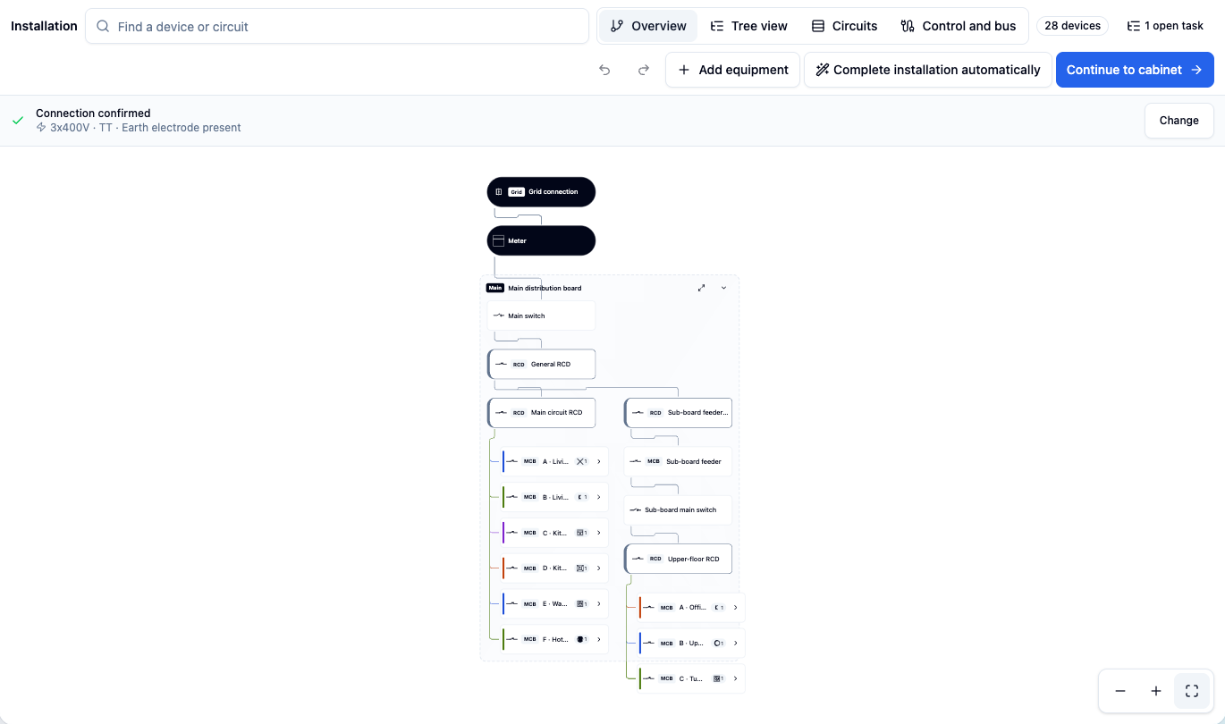
In Installation, Complete installation automatically turns the placed consumers into a proposal with circuits and protective devices; Apply proposal adds it to your project.
- Circuits are grouped by function: lighting, sockets, dedicated circuits.
- Each circuit gets a letter, each point a sequence number (e.g. C1, D1).
- The hierarchy from the supply point to the last consumer is visible.
- Cable type and cross-section appear on every circuit.
Step 4: Derive and export the diagram
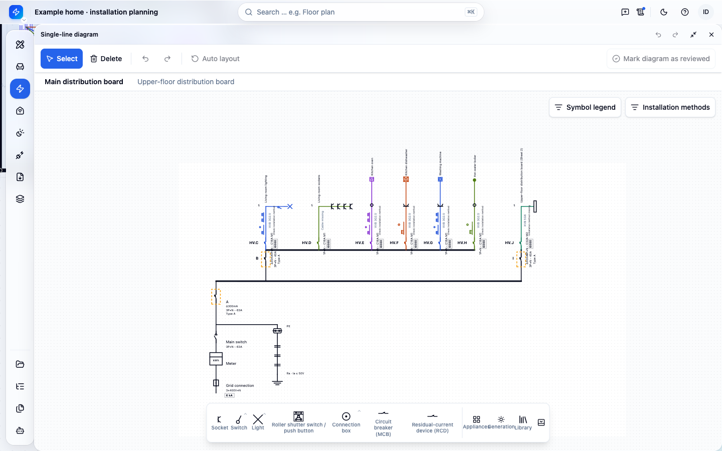
PlanElec builds the single-line diagram from the circuits, protective devices, cables and consumers you entered:
- Readable structure — from the board via the circuits to the consumers
- Symbol catalogue — electrical symbols for the Belgian planning context
- Automatic labelling — circuit references, cable types and protection ratings
- PDF export — single-line diagram and situation plan from the same saved project state
From the survey to one shared reference
For an electrical contractor, the diagram starts with the survey, not with drawing. For each real point, record at least the room, function, circuit and sequence number. Add conductor data and protective-device characteristics as soon as you know them. Anything still missing stays visible in the project as an open review item until you complete or confirm it before export.
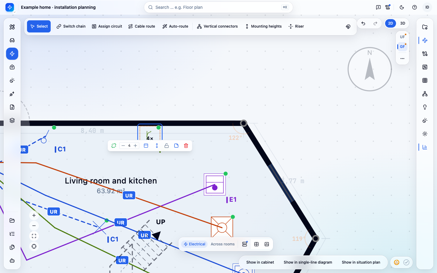
The Installation view connects those entries into an electrical path. You assign an existing floor-plan device to its circuit; there is no need to create a second consumer. You then read the same project data in the single-line diagram and the situation plan.
| On-site survey | Electrical assignment | Diagram representation | Situation-plan check |
|---|---|---|---|
| Device and room, for example a living-room socket | assign the existing floor-plan device to the right circuit | matching catalogue symbol on the circuit branch | same circuit letter and number at the point |
| Circuit and upstream protective device | trace the supply path back to the board | protective device, branch and consumer in order | the point stays at its real location and refers to the same circuit |
| Cable type, cross-section, conductor count and installation method | check the data of the affected cable section | cable information on that section | check the spatial route separately if the section changes |
| Revision, date and open review items | check the saved project state before export | title block, references and visible warnings | read plan and diagram as one document state |
The installation guide on assignment, distribution boards and diagram documents the full workflow with real product views. The following images show two more perspectives of the same fictional project; the labels are sample values.
Example: a single-line diagram as a PDF
The PlanElec example dossier contains a single-line diagram from a fictional project, together with the situation plan and the other export documents. Use it to understand document structure, circuit references and the link to the situation plan. In your own project, every value comes from the real installation.
Common mistakes to avoid
1. Incomplete circuits
Every consumer must be traceable back to the supply point through an unbroken chain of protective devices. Leave no "floating" connections.
2. Wrong symbols
Use the symbols from Table 2.23. Typical mistakes are old DIN symbols or custom notation without a legend. The PlanElec catalogue keeps the representation consistent; the author is responsible for the technical content.
3. Missing information
Every circuit needs:
- circuit letter and point numbers
- cable type, number of conductors and cross-section (e.g. XVB 3G2.5) plus installation method
- rating of the protective device (e.g. 16 A or 20 A); table values are upper limits, so check the conductor sizing in full
- number and type of consumers
4. Outdated diagram
After every change to the installation, you update the single-line diagram or, for a non-substantial change, attach the short description. The approved body signs diagram and plan only once it establishes that the installed work conforms (3.1.2.1 a).
Tips for a clean diagram
- Keep it clear — no unnecessary crossings, no overlapping labels
- Be consistent — the same notation style throughout
- Include every circuit — doorbell and garden lighting too
- State revision and date — every document carries number, revision and revision date (3.1.2)
- Fill in the required details — installation address and the name, capacity and, where applicable, VAT number of the responsible person
Check the required information systematically
Subsection 3.1.2.2 a requires at least the following on a domestic single-line diagram: cable characteristics (type, cross-section, number of conductors), installation method, type and characteristics of residual-current and overcurrent devices, switches, junction and branch boxes, socket outlets, lighting points, fixed machines and appliances, and sources such as solar cell, inverter or battery. Subsection 3.1.2.1 a adds voltage and type of current, the installation address and the details of the responsible person.
A capital letter identifies the elementary circuit. Lighting points, socket outlets and control units get a number in the order they appear in the circuit, starting from the upstream overcurrent device. The situation plan uses the same letter and number. A switch carries the letter of its circuit and the number of the lighting point or appliance it controls. That shared key makes both plans readable together.
A practical circuit walk
Start at the supply and follow each branch to the last consumer. At every transition, ask: does the device really exist, is its function clear, is the cable fully described, and does the reference match the situation plan? Check junction and branch boxes with extra care; a flat list of symbols does not represent a real branch.
With several sources, the grid, PV inverter and any other modelled supply remain readable as separate paths. For PV, PlanElec shows strings per MPPT, DC protection and recorded cable sections in a structured way; unknown or unassigned data stays visible as a gap.
Single-line diagram with solar panels: what must be on it?
Solar panels appear as a source on the single-line diagram: subsection 3.1.2.2 a explicitly lists sources such as the photovoltaic panel, inverter and battery in the minimum content, and the situation plan shows where they are (subsection 3.1.2.3 a). Symbols for the photovoltaic panel and the inverter are in group H of Table 2.23; the characteristics of the sources are either stated on the diagram or kept available in the installation file (note to group H). Domestic low-voltage PV installations up to 10 kVA must also meet the additional requirements of chapter 7.112.
| What | Where | Reference |
|---|---|---|
| Panels, inverter and any battery as a source | single-line diagram | 3.1.2.2 a |
| Location of panels, inverter and battery | situation plan | 3.1.2.3 a |
| User instructions, safety instructions and technical references (brand, model, power) | installation file | 9.1.2 |
| Marking of DC conductors and live AC conductors | installation | 7.112.2 |
| Warning signs stating "Do not disconnect under load" and "Electrical installation always live", or equivalent | installation | 7.112.2 |
| Number and rated power of the panels; number, type, serial number and maximum AC power of the inverter(s) | inspection report | 7.112.4 |
How to work out strings, DC protection and the inverter in detail is covered in PV single-line diagrams in Belgium. If you combine PV with a charger, see Combining Solar PV and an EV Charger on a Single-Line Diagram; the spatial side is in Drawing Solar PV on a Situation Plan.
Existing installations and later changes
For substantial modifications or extensions of a domestic installation, you create or update the single-line diagram and situation plan. For a non-substantial change, a short description with the name, capacity and address of the responsible person, dated and signed, is enough for the diagram; you still show the change on the situation plan (3.1.2.1 a). Parts whose installation began before 1 October 1981 are marked as an "older part" on the diagram. Part 8 contains narrow derogations for existing parts, not a general exemption from documentation or safety.
Electrical correctness before visual polish
Clean lines make the diagram readable; they do not prove the sizing. Cross-section and protection depend on installation method, current-carrying capacity, grouping, temperature, voltage drop, short-circuit conditions and disconnection. The same applies to RCD type, selectivity, surge protection and manufacturer requirements. Use a custom symbol only if it is unambiguous and in the legend; Table 2.23 remains the official basis.
Example of a complete circuit record
"Kitchen" on its own is not a label. A usable record names circuit B, the upstream protective device, the RCD assignment, cable type, number of conductors, cross-section, installation method and the numbered consumers B1 to B6. A hard-wired hob is marked as its own appliance, separate from the general sockets. An existing branch box sits at its real position in the topology.
That makes errors traceable. If B4 is missing from the situation plan, either the plan is incomplete or the diagram has one consumer too many. If cross-section or type change after a box, you describe that section separately; one standard cable for the whole branch would be wrong.
Release check for every sheet
Read the PDF at its real output size. Check the title block, sheet number, revision, date, address, responsible person, voltage and type of current. Then check that no lines or labels are cut off, no symbols overlap and the legend explains every custom sign. Across several sheets, continuations must stay recognisable.
Trace a sample from board to consumer and back: a lighting circuit with a switch, a fixed high-load appliance and a source such as PV. Open or unassigned data stays visible. Never delete a warning just to get a cleaner page.
Who does what
The person responsible for the work prepares diagram and plan, identifies themselves on them and aligns the revision with the installed state. The electrician checks sizing, protection and the real installation. The approved inspection body carries out the inspection and signs once conformity is established. PlanElec provides the project model, the documents and the self-check for this.
Archive and later changes
Keep the inspected revision with situation plan, inspection report and supporting evidence in the installation file. After an extension, you do not overwrite that history: you compare the new design with the inspected state, increase the revision and document the affected circuits. That keeps clear what was already inspected, what was planned and what was actually installed.
The short description of a non-substantial change also goes into the installation file, dated and signed, and the situation plan stays current. If several small changes make the diagram hard to read, you prepare a consolidated new revision and check it in full against the real board.
Official source
- FPS Economy: RGIE/AREI Book 1, Version 06
- Plan content: Section 3.1.2; symbols: Chapter 2.13, Table 2.23; RCD protection: Subsections 4.2.4.3 b and 5.3.5.3 a; main switch: Subsection 5.3.5.1 b
What PlanElec handles for your single-line diagram
PlanElec brings floor plan, electrical topology and distribution board together in one project and derives the single-line diagram and situation plan from them.
- No CAD software needed, everything runs in the browser
- One project model instead of copying data between plan and diagram
- PlanElec Assistant for instructions in your own words; every change runs through the self-check and can be undone in one step
- Advisory AREI/RGIE self-check: it shows you errors in the supported rules that can be decided from project data; the official inspection is done by the approved control body
- PDF export of single-line diagram and situation plan
Related guides
From the guide to your own electrical plan
Create a project and document circuits, cables and protective devices. Check the result against the actual installation.
Fictitious sample dossier, available without sign-up.