Planning
Which comb busbar fits my board? Types, notation and selection
Comb busbar types at a glance: read pole sequence, pitch, fork or pin, cross-section and length, find the right form for a star network, the Belgian 3×230 V delta network and a single-phase supply, and choose it in the cabinet editor.
 AuthorStephan Behm
The right comb busbar depends on three questions: which network conductors does your supply provide (star network 3N~400/230 V, delta network 3×230 V without N, or single-phase)? Which pole layouts do the devices in the row have? And which tooth sequence, pitch and connection type does the busbar have? This article shows the 13 forms the cabinet editor knows, assigns them to situations and explains how to make the choice in the editor. Type numbers come from manufacturer documents (Hager, Schneider Electric, FTG via Vander Elst, Siemens, Eaton; ABB and Gewiss only as dealer listings), as of 13/11/2026. They are not a recommendation and do not replace the datasheet of your devices.
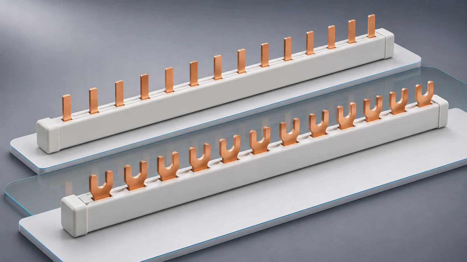
What does a comb busbar distribute, and what does it not?
A comb busbar (also phase rail) connects several devices mounted side by side to a common supply. Each tooth sits on a pole of a device and carries the network conductor of that pole. It replaces wiring from device to device, but neither the supply nor the protective devices.
Three levels can all be called “L1”:
| Level | Question | Example |
|---|---|---|
| Network conductor of the supply | Which conductors does the service connection provide? | Star network: L1, L2, L3, N. Delta network: L1, L2, L3, no N |
| Network conductor at the pole | Which conductor lies on which device pole? | Follows from the tooth sequence of the busbar |
| Marking on the terminal | What kind of pole is the terminal? | “L1” on a 1P MCB: lies on L1, L2 or L3, depending on the tooth |
The marking on the terminal never tells you which network conductor is present. In the delta network, the “N” terminal of a 1P+N device even carries a second line conductor.
What is the comb busbar called in catalogues and at the wholesaler?
| Language | Terms in catalogues and datasheets | Source |
|---|---|---|
| English | comb busbar, phase rail, insulated busbar | Hager catalogue international |
| Dutch | kamrail (Hager), kamgeleider and faserail (Vander Elst) | Hager datasheet (nl); Vander Elst datasheets |
| French (Belgium) | barre de pontage (Hager Belgium), peigne de raccordement (Schneider, Vander Elst), peigne d’alimentation (Legrand) | Hager datasheet fr-BE; Schneider and Legrand catalogues |
| German | Phasenschiene (Hager), Kammschiene (trade, PlanElec) | Hager catalogue DE |
For databases and exports, ETIM class EC000215 applies; Vander Elst lists it as “Faserail” or “Peigne de raccordement”.
How do you read the notation of a comb busbar?
| Detail | Meaning | Example from datasheets |
|---|---|---|
| Pole layout | Which conductors the busbar carries: 1P, 2P, 3P, 3P+N (“3 phases plus N”) or 4P | Hager KDN363A: 3P. Hager KDN463A: 4P |
| Pole sequence (tooth sequence) | Order of the conductors from division unit to division unit | L1·L2·L3 (Hager KDN363A). L1·L2·L3·N (Hager KDN463A). L1·N·L2·N·L3·N (Hager KDN451D) |
| Position of N | For busbars with N: N to the right or left of the line conductor. This depends on the manufacturer | Hager, FTG and Siemens: N right. Schneider: N left (R9XFH412: N·L1·L2·L3) |
| Group busbar (“IN/OUT”) | The busbar changes its pole layout: a head under the RCD, then the outgoing ways | Hager KDN450D: head L1·L2·L3·N, then L1·N·L2·N·L3·N |
| Omitted position | A place without a tooth, for example under the N pole of a four-pole RCD. This is not an N tooth: the busbar carries nothing there | Hager KDN363F: head L1·L2·L3·—, then L1·L2·L3 (four-pole RCD plus eight 1P MCBs on 12 TE) |
| Pitch (division) | Distance between contacts. One division unit (TE) is one module. At half pitch (½ TE), two poles sit in one TE | FTG Eurovario: pitch 17.8 mm. Schneider: pitch 18 mm. ABB Unibis and Gewiss: half pitch, only as dealer listing |
| Connection type | Fork or pin | Hager KDN363A: fork. Hager KB363A: pin. Siemens 5ST3720: pin, without end caps |
| Cross-section and rated current | Cross-section of the busbar and the current it carries | 10 mm² and 63 A (Hager KDN363A). 16 mm² and 80 A (Hager KDN451D). FTG Eurovario: up to 100 A |
| Length in TE | How many division units the busbar covers | Hager: 12 TE (KDN363A), 18 TE (KDN363G), 54 TE (KDN451E), 57 TE (KDN363B), 58 TE (KDN450E) |
End caps belong to this: Vander Elst points out that comb conductors are supplied without the end covers that ensure IP20 safety. FTG Eurovario is fully moulded and needs none; Siemens 5ST3720 has no end caps either.
Be careful with “4-pole”: the word means something different depending on the manufacturer. Hager calls L1·L2·L3·N four-pole, Vander Elst a busbar with L1+N-L2+N-L3+N. What matters is the written pole sequence, not the pole count.
Which form fits which situation?
The editor knows 13 forms and 39 documented references. The table names the forms as their tiles are called in the editor.
| Form in the editor | Tooth sequence | Pitch | Network | References in the catalogue |
|---|---|---|---|---|
| 1P | L | 1 TE | all | none |
| 2P, N right | L1·N (delta network: L1·L2) | 1 TE | 1×230 V, star, delta | Schneider R9XFH218; FTG ES20610, ES21210; Eaton 215642 |
| 3P | L1·L2·L3 | 1 TE | star, delta | Hager KDN363A, KDN363B, KDN363G, KB363A; Schneider R9XFH312, R9XFH318; FTG ES31210, ES31216 |
| 4P, N right | L1·L2·L3·N | 1 TE | star | Hager KDN463A, KDN463B, KDN480B; FTG ES41210, ES41216, E50.418.101 |
| 4P, N left | N·L1·L2·L3 | 1 TE | star | Schneider R9XFH412, R9XFH457 |
| 3 × P+N, N right | L1·N·L2·N·L3·N | 1 TE | star | Hager KDN451D, KDN451E, KDS563A; FTG ES41210N, ES41216N; Siemens 5ST3720 |
| 3 × P+N, N left | N·L1·N·L2·N·L3 | 1 TE | star | Schneider R9XFH518 |
| 4P → P+N, N right | Head L1·L2·L3·N, then L1·N·L2·N·L3·N | 1 TE | star | Hager KDN450D, KDN450E; FTG ES41210FILS, ES41216FILS |
| 4P → P+N, N left | Head N·L1·L2·L3, then N·L1·N·L2·N·L3 | 1 TE | star | Schneider R9XFH518G |
| 4P → 1P | Head L1·L2·L3·—, then L1·L2·L3 | 1 TE | star | Hager KDN363F; FTG ESFI8LSSO, ESFI8LS16SO |
| 2P, N right, ½ TE | L1·N | ½ TE | 1×230 V, star | ABB ABBBVSU21810, ABBBVSU25510 (dealer listing) |
| 3P, ½ TE | L1·L2·L3 | ½ TE | star, delta | ABB ABBBBSU311210 (dealer listing) |
| 3 × P+N, ½ TE | L1·N·L2·N·L3·N | ½ TE | star | Gewiss GW99002 (dealer listing) |
Star network 3N~400/230 V
The star network provides L1, L2, L3 and N. A single-phase circuit is connected between a line conductor and N.
| Situation | Form in the editor | Note |
|---|---|---|
| Four-pole RCD feeds 1P MCBs | 4P → 1P | The N pole of the RCD sits on the omitted position |
| Four-pole RCD feeds 1P+N or 2P MCBs (2 TE each) | 4P → P+N, N right | After that, 3 × P+N, N right also fits |
| 1P+N or 2P devices with no RCD upstream, 2 TE each | 3 × P+N, N right | The devices spread over L1, L2, L3 in turn |
| Three-pole devices without N | 3P | Also 1P MCBs in turn on L1, L2, L3 |
| Devices with an N pole (3P+N, 4P) | 4P, N right | The editor rejects a 3P busbar: “N pole on line” |
| Two-pole RCD feeds 2P outgoing ways | 2P | All outgoing ways hang on one line conductor |
| Compact 1P+N devices, 1 TE wide | 3 × P+N, ½ TE | Documented only as a dealer listing (Gewiss) |
Delta network 3×230 V without N
The delta network has L1, L2 and L3 but no N. A single-phase circuit is connected between two line conductors. Common practice is a four-pole RCD with a free N pole; PlanElec creates new RCDs on a three-phase supply as four-pole and leaves the N pole free in the delta network. This is not a manufacturer requirement. The two-pole RCD remains selectable.
| Situation | Form in the editor | Note |
|---|---|---|
| RCD feeds 2P MCBs (2 TE each) | 3P | A 2P device takes two consecutive teeth: L1·L2, L3·L1, L2·L3. Forms with N: “Other network” |
| Three-pole devices | 3P | Vander Elst explicitly specifies the three-pole comb conductors for the 3×230 V supply |
| Compact 2P devices, 1 TE wide | 3P, ½ TE | Documented only as a dealer listing (ABB Unibis) |
| Two-pole RCD feeds 2P outgoing ways | 2P | One pair of conductors |
On single-phase and two-phase circuits in domestic installations, the regulations say (AREI Art. 4.4.4.2): overcurrent detection is provided on both active conductors, unless at this level there is a residual-current protective device that also contains overcurrent detection on one of the line conductors and ensures the disconnection of both active conductors; this device has the required breaking capacity. You can read the text in the regulations.
Single-phase supply
In single-phase, the supply provides L1 and N (or L1 and L2). The editor rejects forms that distribute over several line conductors.
| Situation | Form in the editor | Note |
|---|---|---|
| All outgoing ways two-pole (2P or 1P+N, 2 TE) | 2P | Vander Elst explicitly specifies two-pole types for 1×230 V |
| Compact 1P+N devices, 1 TE wide | 2P, ½ TE | Documented only as a dealer listing (ABB Unibis) |
When does a form not fit?
In the editor, tiles that do not fit appear dimmed; the reason is behind the info icon.
| Message in the editor | Meaning |
|---|---|
| Other network | The form is documented for a different network type, for example an N tooth in the delta network |
| Single-phase supply | The form distributes over several line conductors |
| Pitch mismatch | The pole spacing of the devices differs from the pitch of the form |
| Tooth missing | A line pole would sit on a position without a tooth |
| Line on N tooth | A line pole would sit on an N tooth |
| N pole on line | An N pole would sit on a line tooth |
| N side mismatch | Form with N left, devices with N right |
| Line twice | A multi-pole device would get the same line conductor twice |
| Head does not fit RCD | The head of the group busbar does not match the poles of the RCD |
| RCD supplies too few | The outgoing ways need more line conductors than the RCD supplies |
| No devices | No outgoing ways are selected |
Two consequences: a two-pole RCD cannot distribute three line conductors, and a 3P busbar without omission cannot feed a four-pole device, because its N pole would sit on a phase tooth.
Which selection mistakes are most common?
| Mistake | Consequence | How to avoid it |
|---|---|---|
| “4-pole” ordered by pole count | L1·L2·L3·N and L1+N-L2+N-L3+N are different busbars | Compare the written pole sequence in the datasheet with the row |
| N left instead of N right | Schneider busbars have N left, Hager, FTG and Siemens right | Choose devices and busbar of one brand; the editor reports “N side mismatch” |
| Busbar distributes other conductors than assumed | Phase load and voltage do not match the plan | Check the network conductor at the pole, not the marking on the terminal |
| Fork and pin mixed up | The busbar does not match the device’s connection type | Derive the connection type from the device terminal and choose according to the datasheet |
| Pitch and manufacturers mixed | Pitch 17.8 mm at FTG, 18 mm at Schneider: the fit is not documented | Use busbar and devices of the same manufacturer; Schneider names the compatible ranges per busbar |
| Devices with an auxiliary contact on a standard busbar | Vander Elst and Legrand exclude them; Hager offers dedicated busbars | Choose a busbar released for auxiliary contacts |
| Three-pole busbar for devices with an N pole | Vander Elst: “Suitable for devices with N conductor: No” | Choose a form with N |
| Rated current of the busbar overlooked | 10 mm² and 63 A versus 16 mm² and 80 A: the busbar has its own current limit | Compare the busbar’s current with the current at the infeed point |
| Open teeth and ends not covered | Free teeth stay unprotected, ends without a cap are open | Fit covers (“Kamrailafscherming voor vrije aansluitpolen” at Hager) and end caps if the busbar has none |
How do you choose the comb busbar in the cabinet editor?
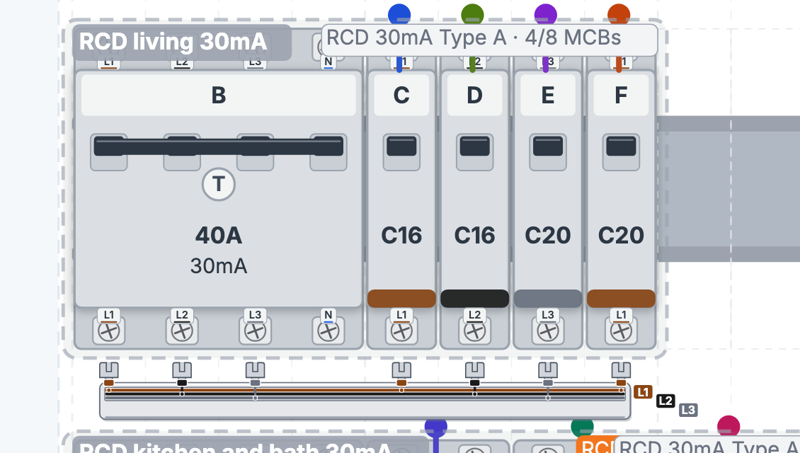
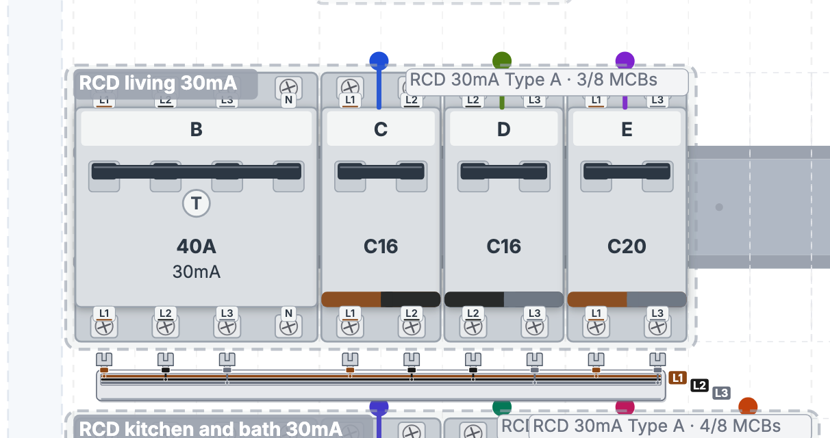
The wiring tools are in pilot status. You see and change the comb busbar in the studio under Distribution board in the Wiring workspace. Every busbar is drawn with coloured lanes per network conductor and teeth in the colour of their conductor; the terminal marker on the device shows the network conductor of the pole, and the terminal marking appears in the tooltip (“Terminal … · Supply conductor …”).
Read the card at the busbar
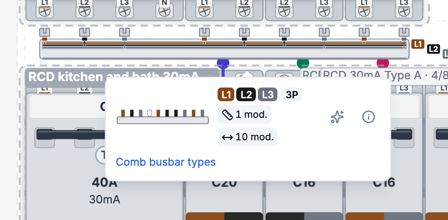
- Click the busbar. The Comb busbar card opens.
- The card shows a miniature and chips: the Conductors (L1, L2, L3, N), the form (for example “4P → 1P”), manufacturer and type number, Pitch and Length in modules. A symbol tells you whether the busbar is derived (Automatic) or Saved.
- The info icon (“Why this type”) shows the reasons. At the bottom, the card links to this article (“Comb busbar types”).
| Reason in the card | Meaning |
|---|---|
| N via busbar | The busbar carries N itself |
| N via neutral block | N comes in via a neutral block |
| N pole without tooth | The N pole of the RCD sits on an omitted position |
| Delta: pairs, no N | In the delta network there are conductor pairs and no N |
| Fourth pole free | The fourth pole of the RCD stays unoccupied |
| Two poles per module | Half pitch |
| 2P RCD: one conductor | The RCD passes on only one conductor |
| Fixed to L1 (L2, L3) | The outgoing ways are fixed to one conductor |
| Single-phase supply | There is only one line conductor |
| Saved pattern | The busbar comes from the saved project |
Resolve a conflict with a two-pole RCD
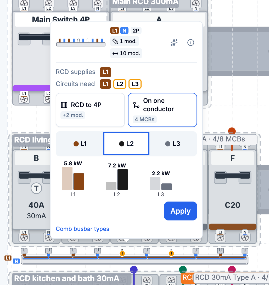
If an outgoing way needs more line conductors than the RCD supplies, the busbar shows a warning sign (“RCD does not supply every conductor”). The card shows what the RCD supplies, what the circuits need and what is Missing. There are two ways:
| Way | Effect |
|---|---|
| RCD to 4P | The RCD becomes four-pole; the card gives the extra space in modules (for example “+2 mod.”) |
| On one conductor (delta network: On one pair) | You choose the Conductor or Conductor pair, the Phase load bars show Before and After in kW, then Apply |
A way can be blocked: “No room in the row”, “Article is 2-pole only” (“Already 4-pole” for an RCD that already has four poles), “Conductor does not fit” or “Not applied”. If three-pole outgoing ways remain, the card says “n × 3P remains”.
Choose the form in the busbar editor
- In Wiring, choose the Comb busbar tool and the devices of one row. Only MCBs and RCBOs can belong to a busbar group.
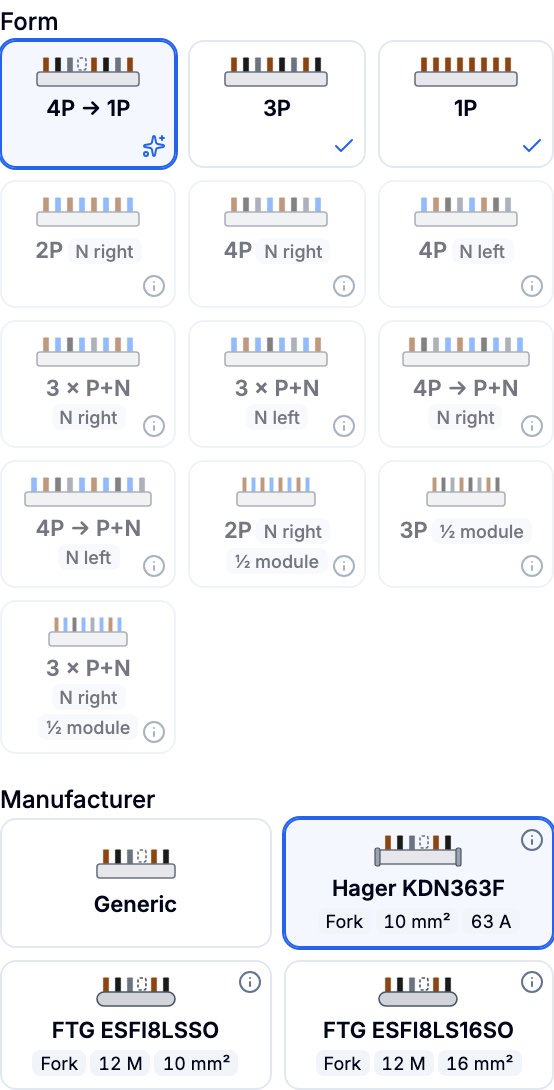
- In the Physical busbar group panel, the Form section shows the forms as tiles with a miniature. Fitting ones come first, the best carries a star (“Best fit”), non-fitting ones are dimmed; the reason is behind the info icon.
- Below, Manufacturer shows Generic and the references of the chosen form with chips for fork or pin, modules, cross-section and current. The origin (“Datasheet”, “Manufacturer page”, “Dealer listing”) is in the tooltip. The reference is optional.
- A new busbar starts with the best form; if there is a reference from the board’s brand, it is preselected, otherwise Generic applies. The choice sets pole sequence, pole count and pitch.
- The status Verified, Unverified or Incompatible shows whether manufacturer data supports the form. Check the preview and click Apply.
In the bill of materials, the busbar appears with manufacturer and type number (“Comb busbar Hager KDN451D”) or, without a reference, as “Comb busbar 3 × P+N, 12 modules, 1 module pitch (generic)”.
What are the limits of the editor?
- The tables show documented forms and references, not a complete type list. Only what the research of 13/11/2026 confirmed is included. Other manufacturers and ranges have their own tooth sequences.
- Legrand and the ABB ranges BV-G and BV-S are missing: no tooth sequence is documented for them. For the ABB half pitch (Unibis) and Gewiss there are only dealer listings.
- Busbars with two pitches in one piece (Schneider Resi9 XP, Hager narrow design) cannot be represented by the editor.
- Vertical connectors between DIN rails are not part of the editor.
- N left: the forms with N left are documented (Schneider) but today fit no modelled device, because devices in the model carry N on the right.
- A reference supports the form, not suitability for arbitrary devices. How the busbar physically ends at the free N pole of a four-pole RCD in the delta network is not documented in any datasheet; ask the manufacturer.
- Module counts differ by market (Hager KDN451E: 54 TE per the Belgian datasheet, 57 TE in the older ordering guide). Your wholesaler’s datasheet is authoritative.
- PlanElec plans the cabinet wiring in pilot status. The acceptance of the installation is carried out by the approved inspection body.
Continue with Plan the installation and form sub-boards and Recognise a distribution board from photos.
Sources
All details on types, pole sequences, pitch, cross-section and current come from manufacturer documents retrieved on 13/11/2026. The product catalogue carries the evidence URL for every reference.
- Hager, Bestellübersicht Modulargeräte, as of 11/2023: tooth sequences of KDN363A, KDN363F, KDN463A, KDN451D, KDN450D.
- Hager datasheets: KDN363A (fr-BE), KDN363A (nl), KB363A (nl-BE).
- FTG, Eurovario catalogue 07/2025; Vander Elst (Ftg datasheets), for example three-pole for 3×230 V, two-pole L-N for 1×230 V, three-pole + N.
- Schneider Electric, Resi9 XB (R9XFH…): datasheets via the evidence URLs in the catalogue. Legrand, Peigne bipolaire équilibré sur 3 phases: term and exclusion of auxiliary contacts.
- AREI Art. 4.4.4.2: regulations, part 4.
Important for electrical planning
These guides explain the software workflow. Have the design, installation and documents reviewed by a qualified electrician where needed; only an accredited inspection body performs the official inspection.
Continue reading
Getting started: from a new project to your first PDF
Create a project, choose the floor plan or the single-line diagram as your starting point, use guidance, a template or AI floor plan recognition, and produce your first draft PDF.
Using and reviewing automatic planning
Use PlanElec proposals for devices, switch chains, cable routes, circuits, phases, and the distribution board without skipping technical review.