From floor plan to installation and distribution board
The new installation tree connects existing devices, protection paths, distribution boards and documents in one planning workflow.
 AuthorStephan Behm
A device in the floor plan shows where it is. The new Installation view also makes clear what supplies and protects it. The same devices then form the basis for distribution boards, cabinet layouts and the single-line diagram. You enter each consumer only once.
Plan the electrical structure before choosing the cabinet
Electrical structure and physical implementation answer different questions. A circuit can already be planned while its board, enclosure or row layout remains open. These drafts survive saving and reloading, with incomplete work kept visible.
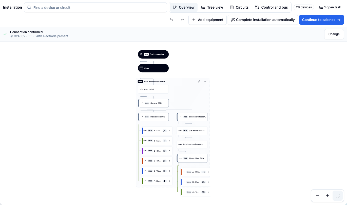
Select a consumer to see its supply and protection path. Search and collapsible branches make the installation easier to read. The tree view also keeps planning actions accessible on narrow screens.
An example using existing devices
In the fictional example, an existing living-room socket receives its circuit assignment. The related upper-floor protective devices are then selected. A preview shows the entry point, modules and assignment effects before the distribution board is created.
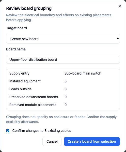
The confirmed frame represents the physical board and its built-in devices. Supplied sockets and lights remain outside it. A feeder is explicitly planned with its protective device and cable information; drawing a frame does not invent equipment.
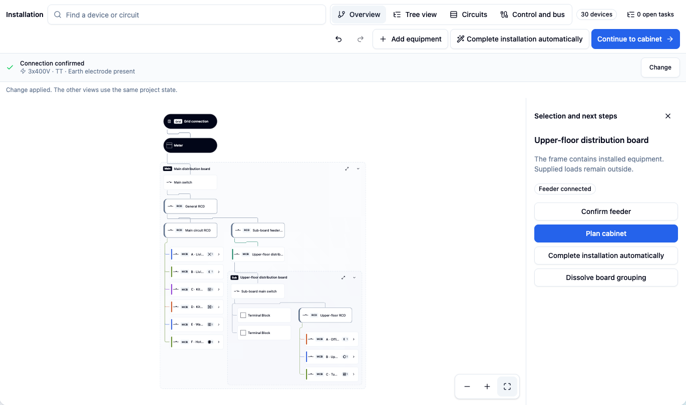
Continue with the same project
| Next view | Result |
|---|---|
| Cabinet | Detail modules, rows and an enclosure using recorded space assumptions |
| Single-line diagram | Review the same electrical installation on document sheets |
| Export | Produce documents from the saved version with a visible status |
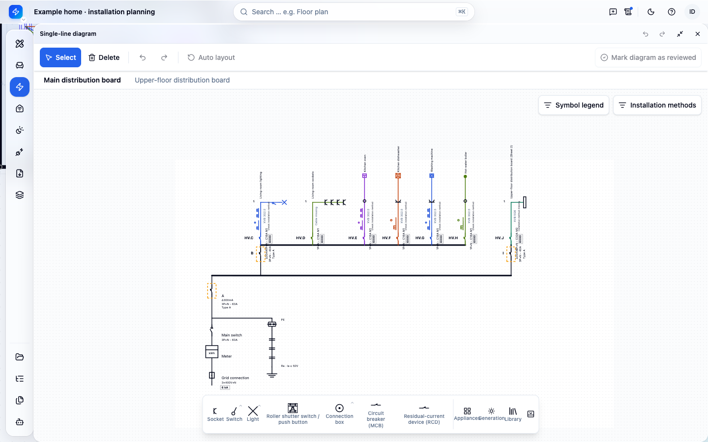
Enclosure proposals use module requirements, your reserve and accessory allowance. Generic devices or missing installation conditions keep the result an estimate. Once you record manufacturer data and installation conditions, the proposal becomes specific. Diagram and dossier deliver the documents; the electrician signs off the design and the recognised inspection body carries out the inspection.
What happens to existing projects?
Existing devices and boards remain usable. The new view presents their electrical structure as one continuous installation; the Board Editor remains editable for its concrete layout. The suggested sequence is a starting point, not a gate: you can continue working in whichever view suits your task.
The illustrated guide covers assignment, open drafts, distribution boards, feeder planning, cabinets and export step by step.