Power to the garden shed or garage: how do I plan and draw the buried cable and sub-board under the AREI/RGIE?
Buried cable at least 0.60 m deep or mechanically protected, sub-board labelled and shown on the situation plan, degree of protection according to water: how to plan the supply of a garden shed, garage or carport under the Belgian AREI/RGIE and draw it in PlanElec Sketch.
 AuthorStephan Behm
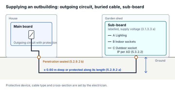
A garden shed, a detached garage or a carport gets its power from its own outgoing circuit in the main distribution board, a buried cable and, as soon as several circuits are needed, a sub-board. The AREI/RGIE requires a minimum depth of 0.60 m for the buried cable or, where that is technically impossible, continuous mechanical protection (sub-section 5.2.9.2 a). The sub-board is labelled (sub-section 3.1.3.3 a), shown with its location on the situation plan (sub-section 3.1.2.3 a) and given its own section in the single-line diagram. You can draw it for free in PlanElec Sketch; installation, sizing and inspection remain the job of the electrician and the accredited inspection body.
Status 7 November 2026, AREI/RGIE Book 1 version 07. The AREI (Dutch) and RGIE (French) are the Belgian general regulations on electrical installations. Written by the PlanElec team, which builds Sketch and Pro.
Do I need a sub-board, or is one circuit enough?
That depends on what goes into the outbuilding. The AREI/RGIE does not require a sub-board; it sets how circuits, wiring and boards are installed and documented.
| Use in the outbuilding | Typical solution | What appears on the diagram |
|---|---|---|
| One light and one socket in the garden shed | One final circuit from the main board | One circuit with letter, protective device and buried cable |
| Lighting, several sockets, a workbench in the garage | Feeder cable to a sub-board with its own circuits | Outgoing circuit in the main board, feeder, sub-board with circuits |
| EV charging point under the carport | Dedicated circuit; details in EV charger under the AREI | Dedicated circuit with charging point |
| Pond or well pump | Appliance in a fixed location, often on its own circuit | Circuit with fixed appliance |
For sockets, the same limit applies as in the house: at most eight single or multiple socket outlets per final circuit (sub-section 5.3.5.2 b, see How many sockets per circuit?). Which appliances need a dedicated circuit is listed in Dedicated circuits for appliances.
How deep must the cable to the garden shed be buried?
Sub-section 5.2.9.2 a covers underground wiring:
| Requirement | Content |
|---|---|
| Suitable cables only | In the ground and in inaccessible underground ducts, only cables complying with the applicable standards (except independent protective conductors) |
| Minimum depth | 0.60 m below the surface (ground level, top of paving or road surface), unless technically impossible |
| If 0.60 m is not possible | Protection by a continuous duct or an equivalent system of durable, resistant material |
| Cable protection (one of three conditions) | earthed screen and armour or reinforced outer sheath; or resistant outer sheath plus a continuous cover above the cable against tools; or laying in a duct |
| Wall penetration | Carefully seal the hole after laying (sub-section 5.2.9.2 b) |
| Telecommunication cables | At least 0.50 m distance from existing telecommunication cables (sub-section 5.2.9.2 c.1) |
Which cable meets these conditions and which cross-section is needed is decided by the electrician. Long runs through the garden make voltage drop relevant; how to estimate it is shown in Calculating voltage drop, and matching cross-section to protection in Cable cross-section and circuit breaker.
May the cable run along the façade or the fence?
In the open air and surface-mounted, only cables may be installed; independent protective and bonding conductors and independent earthed live conductors such as PEN are exempt (sub-section 5.2.9.5). Fixings must keep the wiring undamaged and withstand the external influences. Outside buildings, installation follows good practice, taking the external influences into account (sub-section 5.2.9.14). A cable on the façade appears on the single-line diagram with its installation method; the available codes are explained in Installation methods under the AREI.
What degree of protection do outdoor sockets and lights need?
The degree of protection depends on the presence of water where the equipment is used, which the AREI/RGIE describes with codes AD1 to AD8 (sub-section 5.3.2.2, table 5.4). Classifying the location is the electrician's job.
| Code | Presence of water | Minimum degree of protection |
|---|---|---|
| AD1 | negligible | IPX0 |
| AD2 | dripping water | IPX1 |
| AD3 | spraying water | IPX3 |
| AD4 | splashing water | IPX4 |
| AD5 | water jets | IPX5 |
Outdoor lighting fittings exposed to AD2 to AD4 may not be class 0 or 0I (sub-section 5.3.4.2 h). Which RCD protects the sockets in the shed is explained in A 30 mA RCD for every socket?.
How does the sub-board appear on the single-line diagram and the situation plan?
| Where | What belongs there | Reference |
|---|---|---|
| Single-line diagram | Outgoing circuit in the main board with protective device, feeder cable with type, cross-section, number of conductors and installation method, sub-board with its circuits, protective devices and loads | sub-section 3.1.2.2 a |
| Circuit referencing | One capital letter per circuit, points numbered from the protective device | sub-section 3.1.2.1 a |
| Situation plan | Location of the sub-board, sockets, light points, switches and fixed appliances in the outbuilding | sub-section 3.1.2.3 a |
| On the board itself | Individual, indelible labelling and the supply voltage | sub-section 3.1.3.3 a |
| At the protective devices | Every circuit identifiably labelled | sub-section 3.1.3.1 |
The sub-board in the garden shed belongs to the same installation as the house as long as it hangs on the same meter. It therefore gets no diagram of its own, but a section in the diagram of the house. How main and sub-boards are structured is explained in Electrical planning across several floors.
Does the cable route through the garden belong on the plan?
For homes, the AREI/RGIE requires the situation plan to show the location of boards, boxes, sockets, light points, switches and fixed appliances (sub-section 3.1.2.3 a), not the route of a buried cable. Only for non-domestic installations must owners of underground wiring be able to provide its plans or the data needed to locate it (sub-section 3.1.2.1 b). Drawing the route anyway, with the depth and position of the duct, is a good habit: whoever later puts up a fence, plants a tree or builds a terrace knows where not to dig. In Sketch, the Text tool on the situation plan, placed where the cable leaves the house, is enough.
Is this a substantial extension?
An alteration or extension is substantial if it has an additional effect on the safety of persons or property that no conformity inspection has covered yet (section 2.11.2). A new outgoing circuit with a buried cable and its own board brings new protective devices and wiring; agree the classification with your electrician.
| Classification | Plans | Inspection |
|---|---|---|
| Substantial | Draw or update the single-line diagram and situation plan (sub-section 3.1.2.1 a) | Conformity inspection of the added and altered parts before use (sub-section 6.4.7.3) |
| Not substantial | Short, dated and signed description; the situation plan shows the change (sub-section 3.1.2.1 a) | no conformity inspection before use required |
The consequences of alterations to an existing installation are covered in Renovation and electrical plans.
How do I draw the shed and sub-board in PlanElec Sketch?
- Open Sketch with ‘Draw the documents for the inspection’ or your existing drawing of the house. Without an account the drawing stays in the browser.
- In the Single-line diagram, add the outgoing circuit to the shed at the main board and place the Sub-board from the library onto the cable of that circuit. Connect the lighting and socket circuits to the sub-board; Sketch assigns letters and numbers.
- Enter type, cross-section, installation and length on the feeder cable once the electrician has set them; Sketch writes them next to the cable on the diagram. Until then, a note helps.
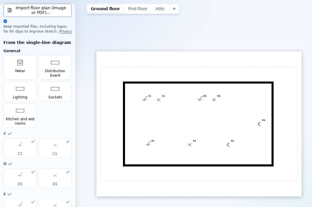
- In the Situation plan, create a separate floor for the outbuilding (Add floor, for example ‘Garden shed’) and drag the sub-board, lights and sockets to their place.
- Check documents shows what is still missing, such as devices without a place on the situation plan. Then Create PDF.
Sketch is free; without an account the PDF carries a logo watermark, and a free account removes it. All limits are on the pricing page.
Sketch or Pro: what do you need?
| Your situation | Tool |
|---|---|
| Owner sketching the extension before talking to the electrician | Sketch, free |
| Electrician delivering the single-line diagram and situation plan of the extension | Sketch |
| Contractor laying out main and sub-board in the board editor and needing a self-check report | Pro, taken over from Sketch with Take it to Pro |
| Cable routes and lengths from the floor plan for the bill of materials | Pro |
What Pro adds with board planning, cable routes and the self-check is shown on the PlanElec Pro product page; how cable routes are created there is explained in the help guide Switch chains, circuits and cable routes.
Limits
This article sets out the AREI/RGIE requirements for buried cables, open-air installation, degree of protection and documentation. It does not size any cable, choose any protective device or assign any location to an AD code; that is the electrician's job. Sketch checks no AREI/RGIE rules. Whether the extension complies is established by the accredited inspection body.
Official source and further reading
- FPS Economy: General regulations on electrical installations (RGIE), Book 1, French version – section 2.11.2, sub-sections 3.1.2.1 a, 3.1.2.2 a, 3.1.2.3 a, 3.1.3.1, 3.1.3.3 a, 5.2.9.2, 5.2.9.5, 5.2.9.14, 5.3.2.2, 5.3.4.2 h and 6.4.7.3
- Distribution board planning guide
- Cable routes and lengths
- Creating a single-line diagram step by step
- Single-line diagram of an existing installation
Draw the documents for the inspection
PlanElec Sketch starts with the supply and the main protection; you draw the rest. Result: single-line diagram and situation plan. The inspection itself is carried out by the accredited inspection body.
Fictitious sample dossier, available without sign-up.